Intel® Server System M50CYP1UR Family System Integration and Service Guide
48
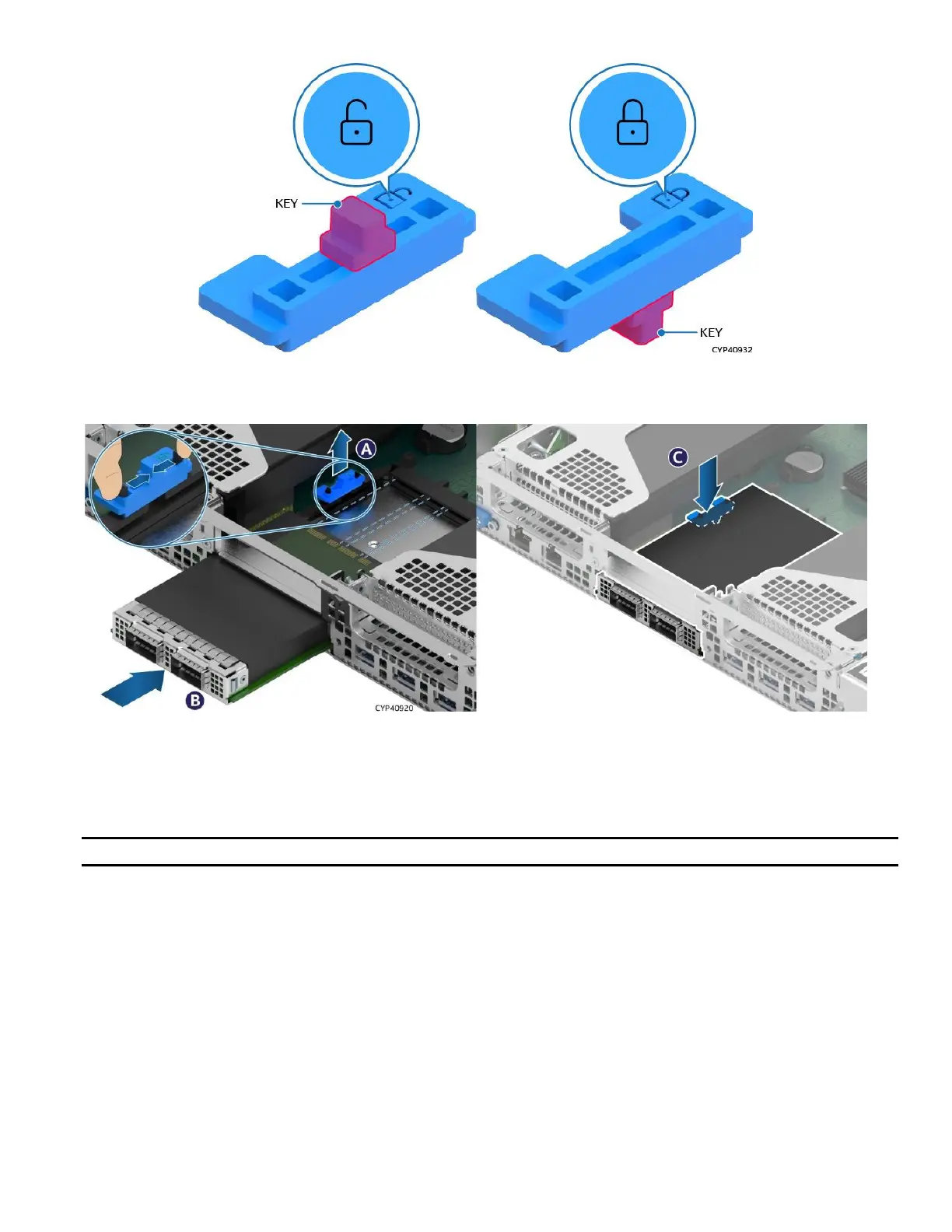
Figure 46. Internal Lock with Unlock and Lock Orientation
Figure 47. OCP* Adapter with Internal Lock Installation
1. Power off the system and disconnect the power cable(s).
2. Remove the system top cover (see Section 3.1.1)
3. Remove any riser card assembly above the OCP* adapter area, if present (see Section 3.2.1).
Note: In the default shipping configuration, the internal lock is set to the unlock orientation.
4. Squeeze the two hooks of the internal lock and pull it out (see Letter A).
5. Align the OCP* adapter with the open OCP* bay slot and slide forward until the connectors make secure
contact (see Letter B).
6. Reinstall the internal lock with the lock orientation (see Letter C).
7. Reinstall the riser card assembly as needed (see Section 3.2.4).
8. Reinstall the system top cover (see Section 3.1.2).
 Loading...


