Intel® Server System M50CYP1UR Family System Integration and Service Guide
74
6.5 Processor Replacement
Components Required:
• New 3
rd
Gen Intel® Xeon® Scalable processor + included shipping tray
• Existing Processor carrier clip
• Existing 1U standard heat sink or 1U Enhanced Volume Air Cooling (EVAC) heat sink + new thermal
interface material (TIM)
Required Tools and Supplies
• Anti-static wrist strap and conductive workbench pad (recommended)
• ESD Gloves (recommended)
• T-30 Torx* screwdriver
• Phillips* head screwdriver #2
6.5.1 Processor Heat Sink Module (PHM) and Processor Removal
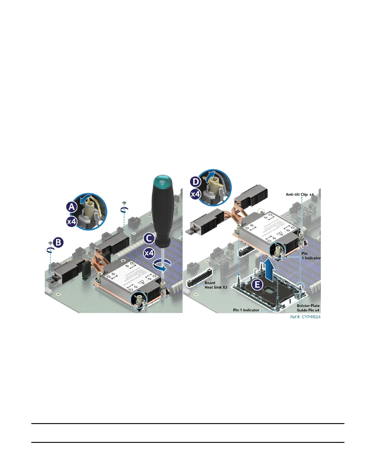
Figure 83. PHM Assembly Removal from Processor Socket
1. Power off the system and disconnect the power cable(s).
2. Remove the system top cover (see Section 6.1.1).
3. Ensure all four heat sink anti-tilt wires are in the outward position (see Letter A).
4. Remove the two screws on the heat sink extension (see Letter B).
5. Then fully unscrew all four heat sink fasteners in any order (see Letter C).
6. Set all four anti-tilt wires on the heat sink to the inward position (see Letter D).
7. Lift the PHM straight up off the server board (see Letter E).
8. After removing the PHM, visually inspect that the socket is free of damage or contamination.
Caution: If debris is observed, blow it away gently. Do not use tweezers or any other hard tools to remove
the debris.
 Loading...


