Intel® Server System M50CYP1UR Family System Integration and Service Guide
40
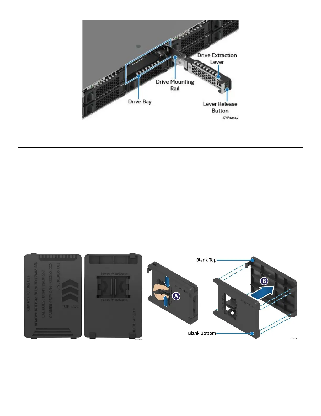
Figure 31. 2.5” Drive Bay Components
Note: To ensure proper system airflow requirements, drive mounting rails must be populated with either a
drive or supplied drive blank.
Note: The 2.5” drive mounting rails in the system are not removable. They slide out so that the storage drives
can be installed or removed in/from them. When sliding out a drive mounting rail from the system, only pull
it as much as it allows without forcing it.
3.3.1 2.5” SSD Drive Assembly for 7 mm Drives
The Intel® Server System M50CYP1UR family supports 2.5” SSDs with 7 mm of thickness when used in
conjunction with the supplied blanks. The supplied blank for 2.5” bays has two parts: top and bottom. The
top part must be attached to the 7 mm drive to fit properly inside the 2.5” bay. This section provides
instructions to attach the supplied blank part to a 7 mm thick SSD.
Figure 32. Separating Top and Bottom Parts of Drive Blank
1. Remove the drive blank from the system (see Section 3.3.3).
2. Press the handles at the bottom part of the drive blank (see Letter A).
3. Separate the top and bottom parts while pressing the handles (see Letter B).

 Loading...


