Intel® Server System M50CYP1UR Family System Integration and Service Guide
76
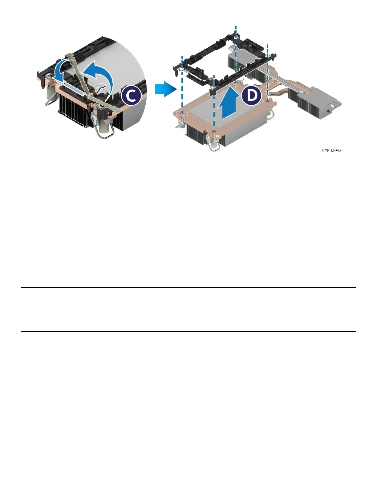
Figure 86. Processor Carrier Clip Removal from PHM Assembly
13. Return the lever to the original position (see Letter C).
14. Unlatch the tab on each corner of the processor carrier clip and lift the clip up to remove the processor
carrier clip from the heat sink (see Letter D).
6.5.2 PHM and Processor Installation
To properly assemble the PHM and install it to the server board, the procedures described in the following
sections must be followed in the order specified. These instructions assume that all the PHM components
are new and the Thermal Interface Material (TIM) is already applied to the bottom of the heat sink.
6.5.2.1 Processor Heat Sink Module (PHM) Assembly
Caution: Wear ESD gloves to prevent electrostatic damage and oxidation or foreign material on processor
package and land pads.
Note: The label on the heat sink refers to PHM installation onto the server board. It does not refer to the
PHM assembly process.
 Loading...


