Intel® Server System M50CYP1UR Family System Integration and Service Guide
23
To properly assemble the PHM and install it to the server board, the procedures described in the following
sections must be followed in the order specified. These instructions assume that all the PHM components
are new and the Thermal Interface Material (TIM) is already applied to the bottom of the heat sink.
2.3.1 Processor Heat Sink Module (PHM) Assembly
Caution: Wear ESD gloves to prevent electrostatic damage and oxidation or foreign material on processor
package and land pads.
Note: The label on the heat sink refers to PHM installation onto the server board. It does not refer to the
PHM assembly process.
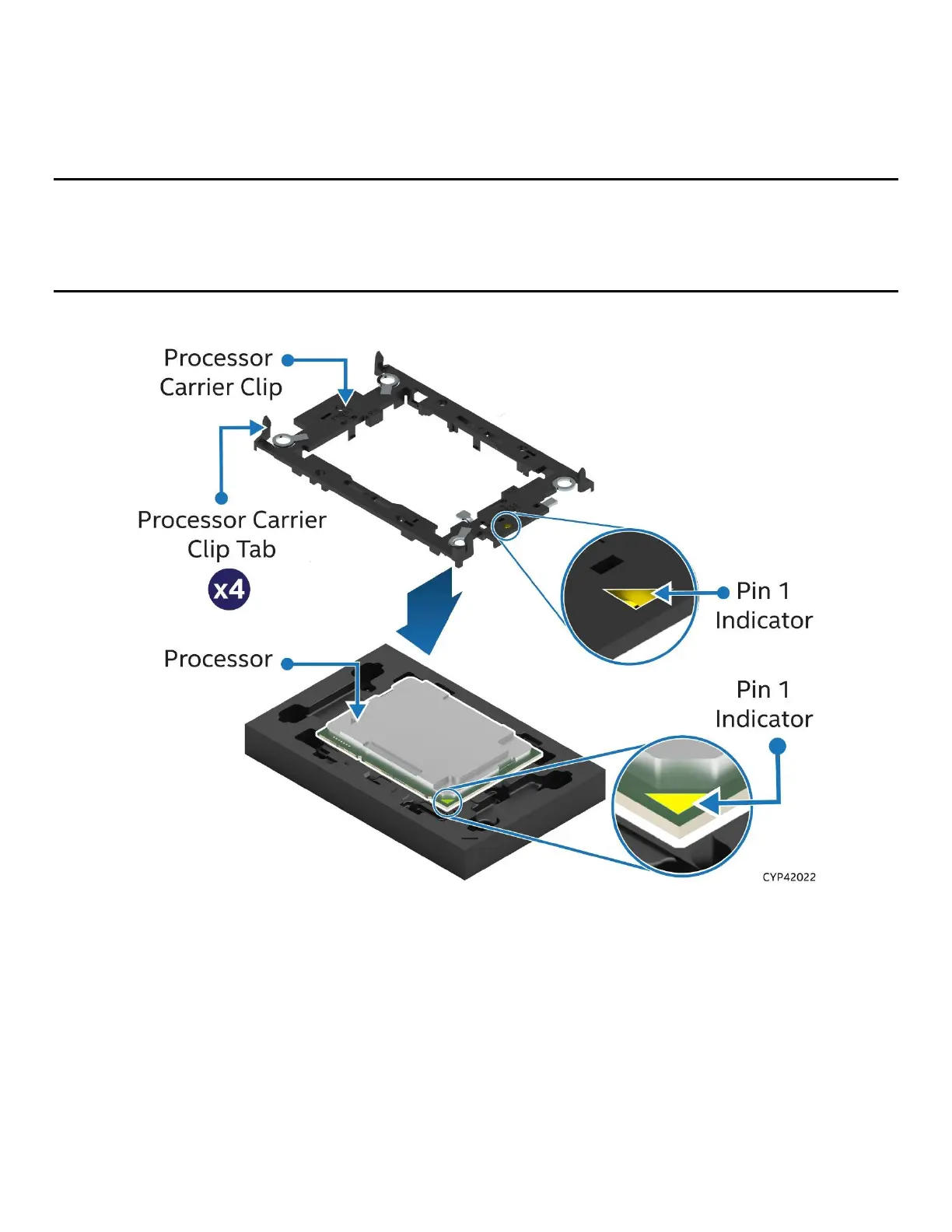
Figure 7. Installing Processor Carrier Clip onto Processor – Part 1
1. Place the processor carrier clip on top of the processor while it is still on the tray.
2. Ensure the pin 1 indicator on the processor carrier clip is aligned with the pin 1 indicator of the
processor.

 Loading...


