Intel® Server System M50CYP1UR Family System Integration and Service Guide
38
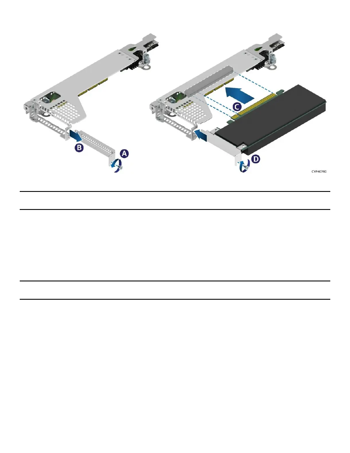
Figure 29. PCIe* Add-In Card Installation for Riser Card on Riser Slot #2
Note: Riser Slot #3 is only used to provide an additional PCIe* NVMe* interface to the hot-swap backplane
mounted to the front drive bay.
1. If the riser card assembly (bracket and board) is still inside the system, remove it from the system
following instructions in Section 3.2.1.
2. Remove the fastener screw (see Letter A) and remove the filler panel from the add-in card slot
(see Letter B).
3. Insert the add-in card until it is fully seated inside the PCIe* slot on the riser card (see Letter C).
4. Using the fastener screws, secure the add-in card to the riser card assembly (see Letter D). Tighten to
5 in-lb.
Note: For add-in cards with internal cable connectors, it may be necessary to connect cable(s) before
installing the riser card assembly into the system. See to Appendix B for cable routing guidance.

 Loading...


