Intel® Server System M50CYP1UR Family System Integration and Service Guide
85
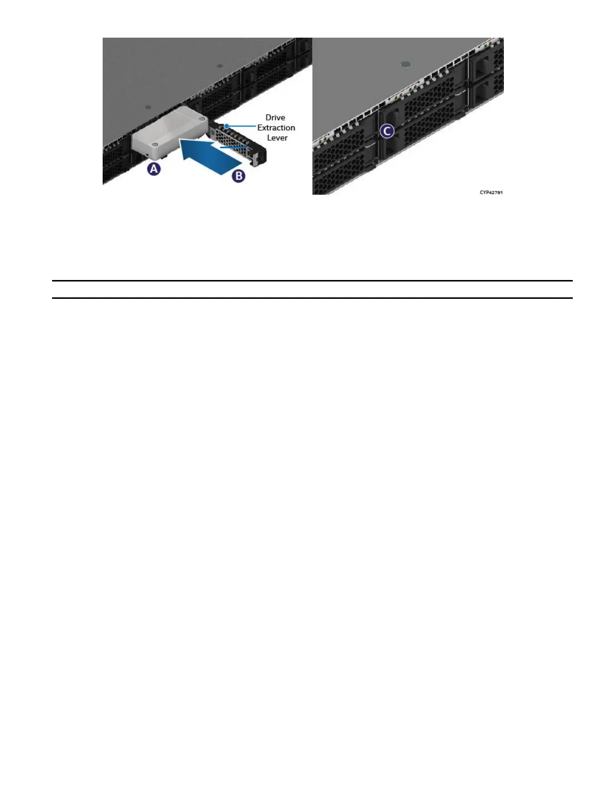
Figure 104. 2.5” 15 mm Drive Installation
6. Ensure the drive extraction lever is in the open position and the drive mounting rail is pulled out half way.
7. Align the drive assembly with the open drive bay.
8. Insert the assembled 7-mm thick drive or non-assembled 15-mm thick drive into the drive bay
(see Letter A).
Note: It is recommended to hold the drive with one hand while holding the lever with the other hand.
9. Slide the drive forward until it contacts the backplane (see Letter B).
10. Complete the drive installation by closing the drive extraction lever until it locks into place (see Letter C).
6.7 Backplane Replacement
The Intel® Server System M50CYP1UR family comes with either a 4 x 2.5” backplane or 12 x 2.5” backplane.
The 4 x 2.5” backplane supports up to four SAS/SATA/PCIe* NVMe drives. The 12 x 2.5” backplane supports
up to twelve SAS/SATA/ PCIe* NVMe* drives. For more information on front drive bay support, refer to the
Intel® Server System M50CYP1UR Family Technical Product Specification (TPS).
6.7.1 4 x 2.5” Backplane Replacement
Required Tools and Supplies
• Anti-static wrist strap and conductive workbench pad (recommended)
• Phillips* head screwdriver #1
 Loading...


