Intel
®
Entry Server Chassis SC5299-E TPS Power Sub-system
Revision 3.1
Intel order number D37594-005
95
The power supply operates within specification over the full range of voltage drops from the
power supply’s output connector to the remote sense points.
2.5.8.3 Output Power/Currents
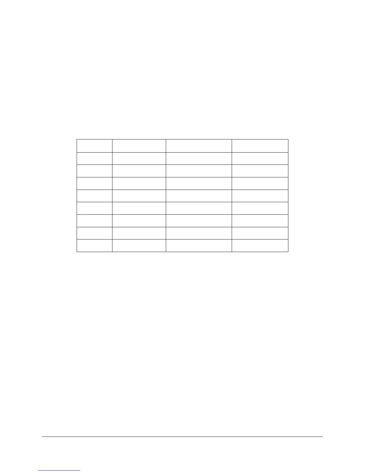
The following table defines the power and current ratings for the 670-W power supply. The
combined output power of all outputs does not exceed the rated output power. The power
supply meets both static and dynamic voltage regulation requirements for the minimum loading
conditions.
Table 116. Load Ratings
Voltage Minimum Continuous Maximum Continuous Peak Load
+3.3V 1.0 A 24 A
+5V
2.0 A 30 A
+12V1 0.5 A 16 A 18 A
+12V2 1.0 A 16 A 18 A
+12V3 0.5 A 16 A 18 A
+12V4 1.0 A 16 A 18 A
-12V 0 A 0.5 A
+5VSB 0.1 A 3.0 A 5A
Notes:
1. Maximum continuous total DC output power should not exceed 670 W.
2. Maximum continuous load on the combined 12V output shall not exceed 48 A.
3. Peak load on the combined 12V output shall not exceed 52 A.
4. Peak total DC output power should not exceed 730 W.
5. For 12V, peak power and current loading shall be supported for a minimum of 12 seconds.
6. For 5Vsb, 5Vsb must withstand 5 A for 500 ms long under first turn-on condition.
7. Combined 3.3V and 5V power shall not exceed 170 W.
2.5.8.4 Standby Output
The 5VSB output is present when an AC input greater than the power supply turn-on voltage is
applied.
2.5.8.5 Voltage Regulation
The power supply output voltages stay within the following voltage limits when operating at
steady state and dynamic loading conditions. These limits include the peak-peak ripple/noise.
All outputs are measured with reference to the return remote sense signal (ReturnS). The
+12V3, +12V4, –12V and 5VSB outputs are measured at the power supply connectors
referenced to ReturnS. The +3.3V, +5V, +12V1, and +12V2 are measured at the remote sense
signal located at the signal connector.