Intel
®
Entry Server Chassis SC5299-E TPS Power Sub-system
Revision 3.1
Intel order number D37594-005
33
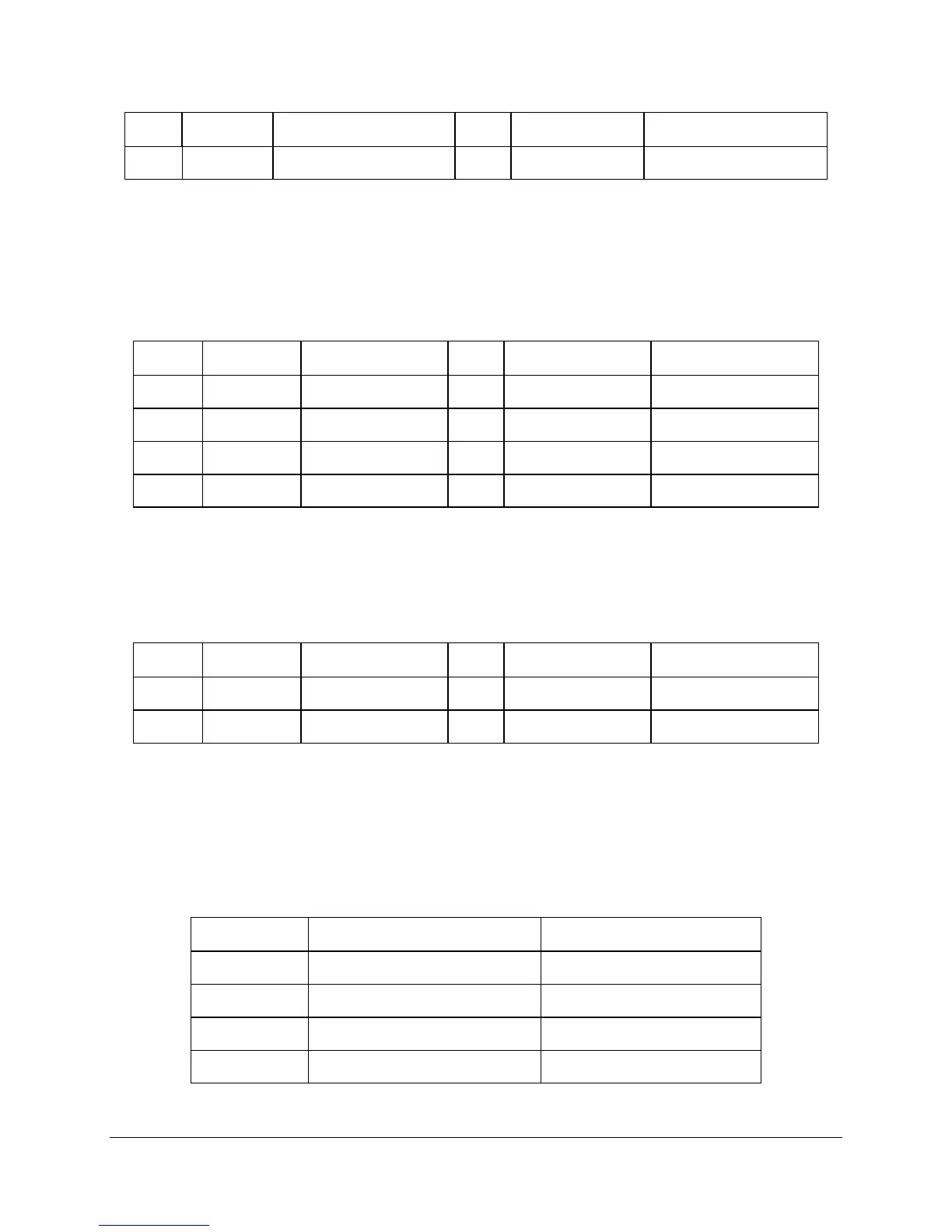
Pin Signal 18 AWG Color Pin Signal 18 AWG Color
12 +3.3 VDC Orange 24 COM Black
Note: 5V Remote sense may be double crimped into pin 4 if required to meet voltage regulation at the output connectors.
2.2.4.3 P2 Processor Power Connector
Connector housing: 8-Pin Molex* 39-01-2085 or equivalent
Contact: Molex
44476-1111 or equivalent
Table 31. P2 Processor Power Connector
Pin Signal 18 AWG Color Pin Signal 18 AWG Color
1 COM Black 5 +12V1 Yellow
2 COM Black 6 +12V1 Yellow
3 COM Black 7 +12V1 Yellow
4 COM Black 8 +12V1 Yellow
2.2.4.4 P12 Baseboard Power Connector
Connector housing: 4-Pin Molex* 39-01-2040 or equivalent
Contact: Molex
Mini-Fit Jr, HCS, 44476-1111 or equivalent
Table 32. P12 Baseboard Power Connector
Pin Signal 18 AWG Color Pin Signal 18 AWG Color
1 COM Black 3 +12V1 Yellow
2 COM Black 4 +12V1 Yellow
2.2.4.5 P3, P4, P6, P7, P8, P9 Peripheral Power Connectors
Connector housing: AMP* 1-480424-0 or equivalent
Contact: Amp 61314-1 contact or equivalent
Table 33. P3, P4, P6, P7, P8, P9 Peripheral Power Connectors
Pin Signal 18 AWG Color
1 +12 V2 Green
2 COM Black
3 COM Black
4 +5 VDC Red