Power Sub-system Intel
®
Entry Server Chassis SC5299-E TPS
Revision 3.1
Intel order number D37594-005
12
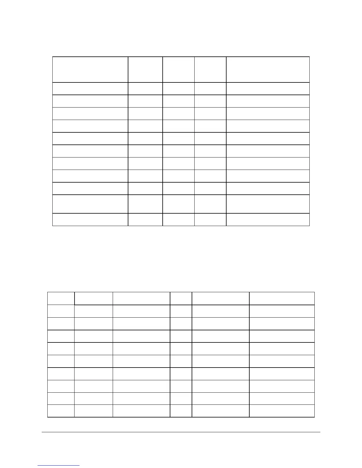
Table 3. Cable Lengths
From
To connector
#
Length
(mm)
No. of pins Description
Power Supply cover exit hole P1 425 24 Baseboard Power Connector
Power Supply cover exit hole P2 425 8 Processor Power Connector
Power Supply cover exit hole P3 250 4 Peripheral Power Connector
Extension P4 100 4 Peripheral Power Connector
Extension from P4 P5 100 4 Floppy Power Connector
Power Supply cover exit hole P6 890 4 Peripheral Power Connector
Extension P7 75 4 Peripheral Power Connector
Power Supply cover exit hole P8 890 4 Peripheral Power Connector
Extension P9 75 4 Peripheral Power Connector
Power Supply cover exit hole P10
890
5
Right-angle SATA Power
Connector
Extension P11 75 5 SATA Power Connector
2.1.3.1 P1 Baseboard Power Connector
Connector housing: 24- Pin Molex* Mini-Fit Jr.
39-01-2245 or equivalent
Contact: Molex* Mini-Fit, HCS, Female, Crimp 44476 or equivalent
Table 4. P1 Baseboard Power Connector
Pin Signal 18 AWG Color Pin Signal 18 AWG Color
1 +3.3 VDC Orange 13 +3.3 VDC* Orange
2 +3.3 VDC Orange 14 -12 VDC Blue
3 COM Black 15 COM Black
4 +5 VDC Red 16 PSON# Green
5 COM Black 17 COM Black
6 +5 VDC Red 18 COM Black
7 COM Black 19 COM Black
8 PWR OK Gray 20 Reserved N.C.
9 5VSB Purple 21 +5 VDC Red