Intel
®
Entry Server Chassis SC5299-E TPS Power Sub-system
Revision 3.1
Intel order number D37594-005
13
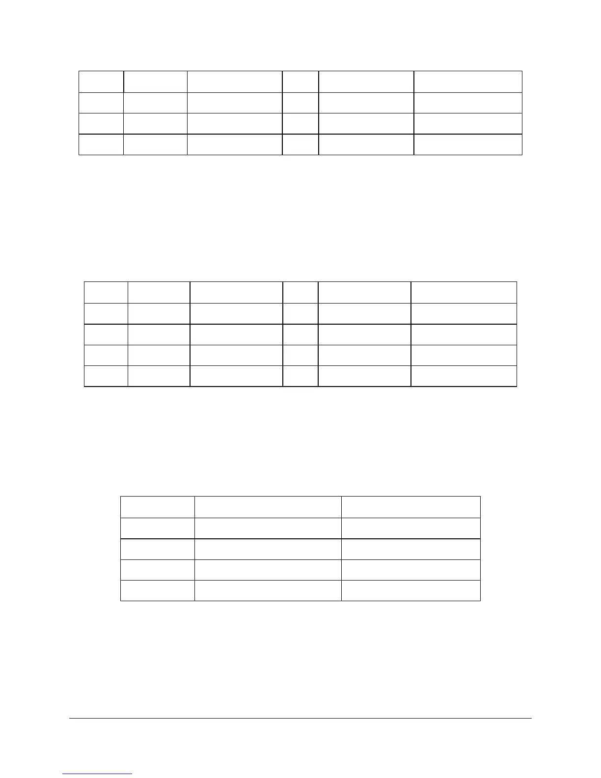
Pin Signal 18 AWG Color Pin Signal 18 AWG Color
10 +12V2 White/Blue Stripe 22 +5 VDC Red
11 +12V2 White/Blue Stripe 23 +5 VDC Red
12 +3.3 VDC Orange 24 COM Black
Note:
3.3V Locate Sense Double Crimped into pin 13 (with #22 AWG Orange/White stripe wire).
2.1.3.2 P2 Processor Power Connector
Connector housing: 8- Pin Molex 39-01-2085 or equivalent
Contact: Molex
44476-1111 or equivalent
Table 5. P2 Processor Power Connector
Pin Signal 18 AWG Color Pin Signal 18 AWG Color
1 COM Black 5 +12V1 Yellow
2 COM Black 6 +12V1 Yellow
3 COM Black 7 +12V1 Yellow
4 COM Black 8 +12V1 Yellow
2.1.3.3 P3-P9 Peripheral Connectors
Connector housing: AMP* V0 P/N is 770827-1 or equivalent
Contact: AMP* 61314-1 contact or equivalent
Table 6. P3-P6, P8-P9 Peripheral Connectors
Pin Signal 18 AWG Color
1 +12 V2 Blue/White
2 COM Black
3 COM Black
4 +5 VDC Red
2.1.3.4 P10 Right-angle, P11 SATA Power Connectors
Connector Housing:
Contact: