Intel
®
Entry Server Chassis SC5299-E TPS Power Sub-system
Revision 3.1
Intel order number D37594-005
61
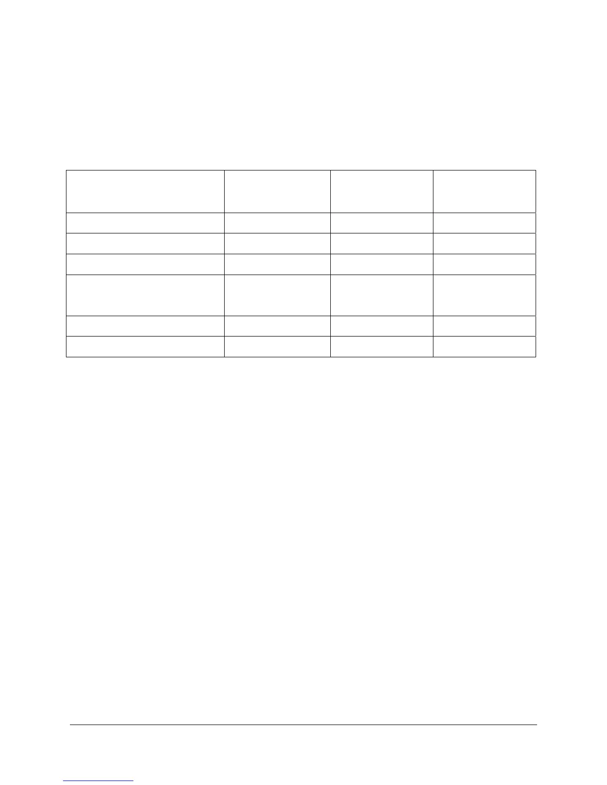
2.3.5.4 LEDs
There is a bi-color LED and a single color LED to indicate power supply status. The LED
operation is defined in the following table.
Table 70. LED Indicators
Power Supply Condition Status LED
(AC OK/Power Supply Fail)
Power Led
(Power Good)
Remarks
AC Power Off OFF OFF
AC power on in Standby Green OFF
AC On and All Outputs in Normal Green Green
Any DC Outputs Short Circuit Green
OFF
Power Distribution
Board protection only;
module OK
DC Fan Not Spinning Amber OFF Module protection only
OTP Amber Green Send out alert signal
The LEDs are visible on the power supply’s exterior face. The LEDs’ location meets
Electrostatic Discharge (ESD) requirements. LEDs are securely mounted in such a way that
incidental pressure on the LEDs does not cause them to be displaced.
There are bits that allow the LED states to be forced via the SMBus. The following capabilities
are required:
Force Amber ON for failure conditions.
No Force (LED state follows power supply present state)
The power-on default is ‘No Force’. The default is restored whenever PSON transitions to
assert.
2.3.6 SMBus Monitoring Interface
The power supply and cage combination provides a monitoring interface to the system over a
server management bus. The device in the power supply is compatible with SMBus 2.0 ‘high
power’ specification for I
2
C V
dd
based power and drive (for V
dd
= 3.3 V). This bus operates at
3.3V but will tolerate 5V signaling.
One pin is used for the Serial Clock [SCL] (PSM Clock). The second pin is used for Serial Data
[SDA] (PSM Data). Both pins are bi-directional, open drain signals, and are used to form a serial
bus. For redundant power supplies, the device(s) in the power supply are located at an
address(s) determined by address pins A0 and A1. The circuits inside the power supply derive
their power from the standby output. For redundant power supplies, the device(s) are powered
from the system side of the or’ing device.