Power Sub-system Intel
®
Entry Server Chassis SC5299-E TPS
Revision 3.1
Intel order number D37594-005
62
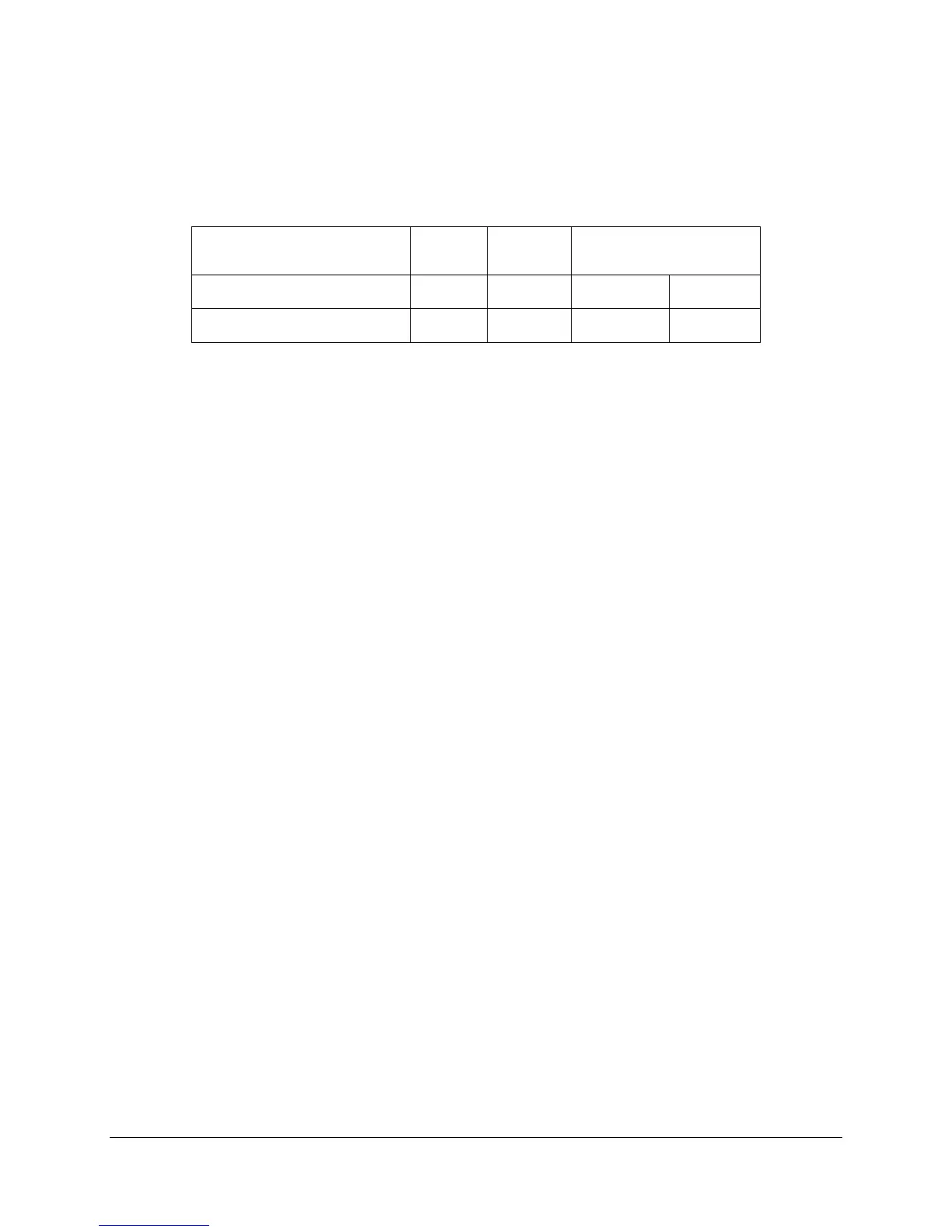
2.3.6.1 Device Address Locations
The power supply plus power distribution board (PS+PDB) device address locations are shown
in the following table. There are two signals to set the address location of the power supply
once it is installed into the system: A0 and A1.
Table 71. SMBus Device Addressing
Reserved for future 2+2
configuration addressing
PDB addressing A0/A1
0/0 0/1 1/0 1/1
Power supply FRU device
A0h A2h A4h A6h
2.4 650-W Power Distribution Board (PDB)
This specification defines the cage for the ERP12V 650-W 1+1 redundant power supply. The
cage is designed to plug directly to the output connector of the power supply(ies) and contains
three DC/DC power converters to produce other required voltages: +3.3VDC, +5VDC and –
12VDC, along with additional 12V rail 240VA protection and a FRU EEPROM.