Power Sub-system Intel
®
Entry Server Chassis SC5299-E TPS
Revision 3.1
Intel order number D37594-005
38
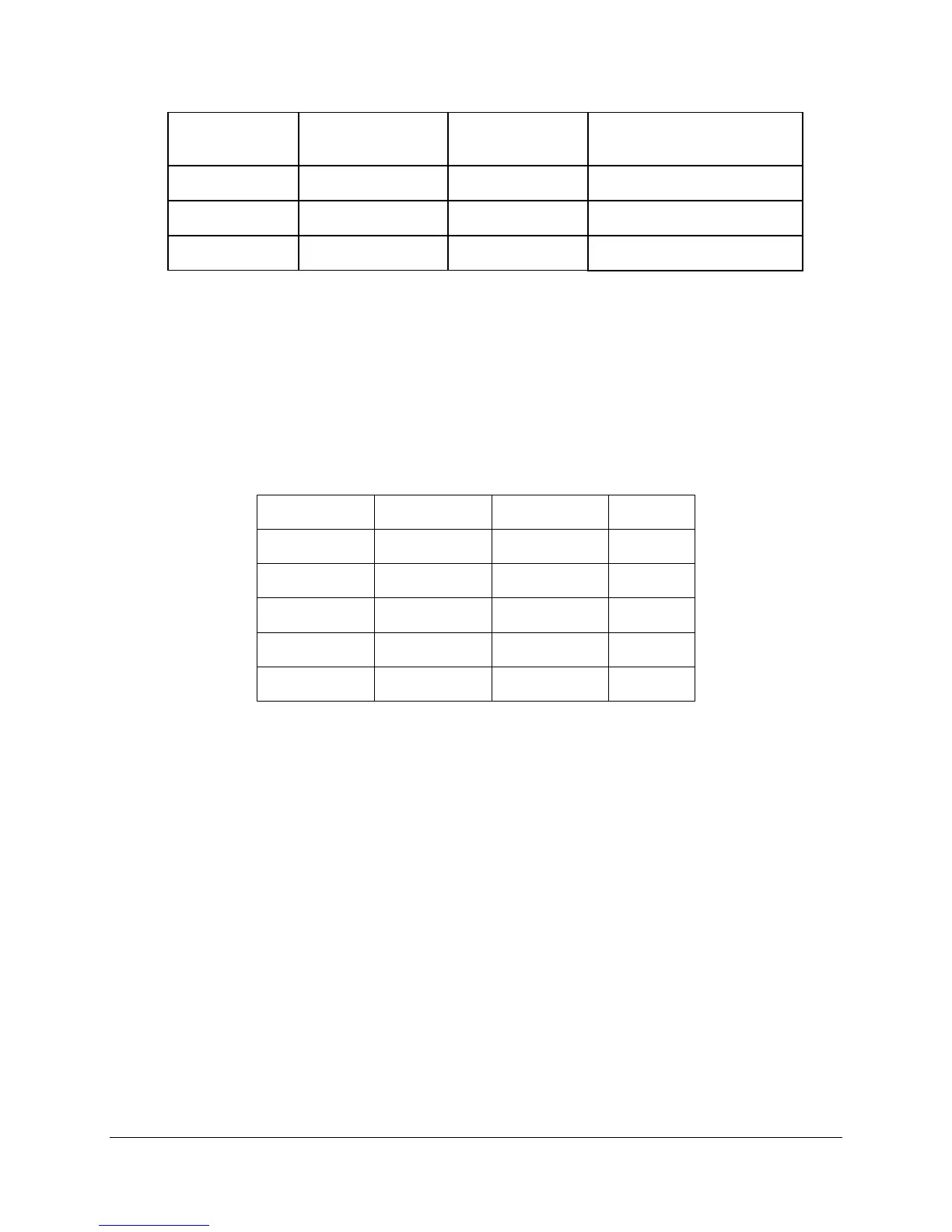
Output Step Load Size (see
note 2)
Load Slew Rate Test Capacitive Load
+12V1 25.0A
0.25 A/ sec 2200 F
1,2
+12V2 25.0A
0.25 A/ sec 2200 F
1,2
+5VSB 0.5A
0.25 A/ sec 20 F
Notes:
1. Step loads on each 12V output may happen simultaneously.
2. The +12V should be tested with 2200 F evenly split between the two +12V rails.
2.2.4.16 Capactive Loading
The power supply is stable and meets all requirements with the following capacitive loading
ranges.
Table 42. Capacitive Loading Conditions
Output MIN MAX Units
+3.3V 250 6,800
F
+5V 400 4,700
F
+12V(1, 2) 500 each 11,000
F
-12V 1 350
F
+5VSB 20 350
F
2.2.4.17 Closed Loop Stability
The power supply is unconditionally stable under all line/load/transient load conditions, including
capacitive load ranges. A minimum of 45 degrees phase margin and -10dB-gain margin is
required. Closed-loop stability is ensured at the maximum and minimum loads as applicable.
2.2.4.18 Common Mode Noise
The common mode noise on any output shall not exceed 350mV pk-pk over the frequency band
of 10Hz to 30MHz.
2.2.4.19 Ripple/Noise
The maximum allowed ripple/noise output of the power supply is defined in the following table.
This is measured over a bandwidth of 0 Hz to 20 MHz at the power supply output connectors. A
10 F tantalum capacitor, in parallel with a 0.1 F ceramic capacitor, is placed at the point of
measurement.