Power Sub-system Intel
®
Entry Server Chassis SC5299-E TPS
Revision 3.1
Intel order number D37594-005
96
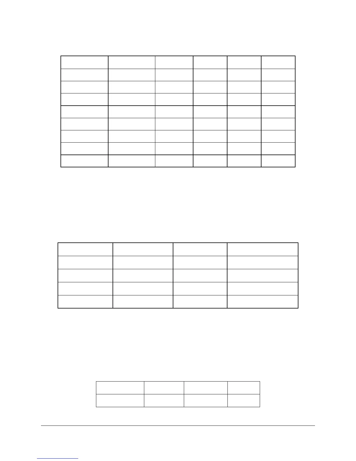
Table 117. Voltage Regulation Limits
Parameter Tolerance MIN NOM MAX Units
+ 3.3V - 5%/+5% +3.14 +3.30 +3.46 V
rms
+ 5V - 5%/+5% +4.75 +5.00 +5.25 V
rms
+ 12V1 - 5%/+5% +11.40 +12.00 +12.60 V
rms
+ 12V2 - 5%/+5% +11.40 +12.00 +12.60 V
rms
+12V3 - 5%/+5% +11.40 +12.00 +12.60 V
rms
+12V4 - 5%/+5% +11.40 +12.00 +12.60 V
rms
- 12V - 5%/+9% -11.40 -12.00 -13.08 V
rms
+ 5VSB - 5%/+5% +4.75 +5.00 +5.25 V
rms
2.5.8.6 Dynamic Loading
The output voltages remain within limits specified for the step loading and capacitive loading, as
shown in the following table. The load transient repetition rate is tested between 50 Hz and 5
kHz at duty cycles ranging from 10%-90%. The load transient repetition rate is only a test
specification. The step load may occur anywhere between the MIN load and MAX load
conditions.
Table 118. Transient Load Requirements
Output Step Load Size
1
Load Slew Rate Test Capacitive Load
+3.3V 7.0A
0.25 A/ sec 4700 F
+5V 7.0A
0.25 A/ sec 1000 F
+12V 25A
0.25 A/ sec 4700 F
+5VSB 0.5A
0.25 A/ sec 20 F
1. Step loads on each 12V output may happen simultaneously.
2.5.8.7 Capactive Loading
The power supply is stable and meets all requirements with the following capacitive loading
ranges.
Table 119. Capacitive Loading Conditions
Output MIN MAX Units
+3.3V 250 6800
F