Power Sub-system Intel
®
Entry Server Chassis SC5299-E TPS
Revision 3.1
Intel order number D37594-005
98
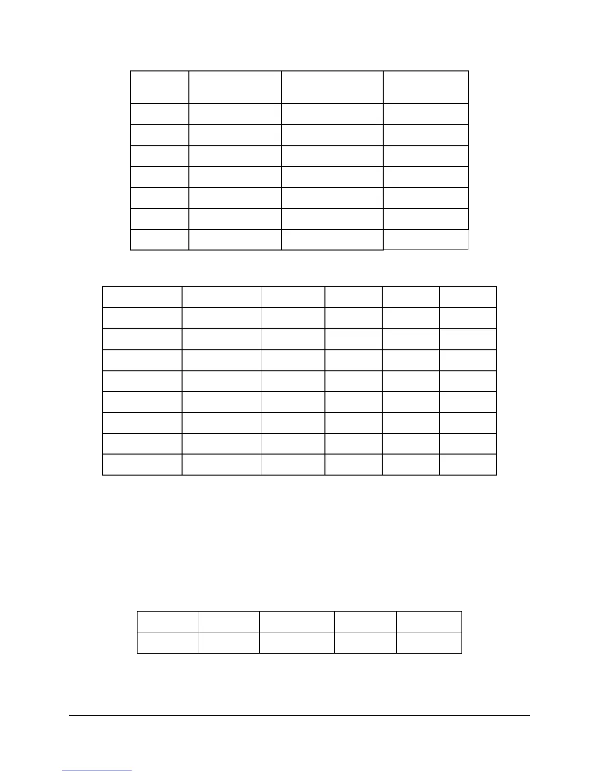
Voltage Minimum Continuous
Load
Maximum Continuous
Load
Peak Load
+5V 0 A 7.0 A
+12V1 0.0 A 8.0 A
+12V2 0.0 A 8.0 A
+12V3 0.1 A 8.0 A
+12V4 0.0 A 8.0 A
-12V 0 A 0.5 A
+5VSB 0.1 A 3.0 A
Table 121. Pre-set Lighter Voltage Regulation Limits
Parameter Tolerance MIN NOM MAX Units
+3.3V - 10%/+10% +2.970 +3.30 +3.630 V
rms
+5V - 10%/+10% +4.500 +5.00 +5.500 V
rms
+12V1 - 8%/+10% +11.04 +12.00 +13.20 V
rms
+12V2 - 8%/+10% +11.04 +12.00 +13.20 V
rms
+12V3 - 8%/+10% +11.04 +12.00 +13.20 V
rms
+12V4 - 8%/+10% +11.04 +12.00 +13.20 V
rms
- 12V - 5%/+9% - 11.40 -12.00 -13.08 V
rms
+5VSB - 5%/+5% +4.75 +5.00 +5.25 V
rms
2.5.8.13 Ripple/Noise
The maximum allowed ripple/noise output of the power supply is defined in the following table.
This is measured over a bandwidth of 10Hz to 20MHz at the power supply output connectors. A
10 F tantalum capacitor, in parallel with a 0.1 F ceramic capacitor, is placed at the point of
measurement.
Table 122. Ripple and Noise
+3.3V +5V +12V (1,2,3,4) -12V +5VSB
50mVp-p 50mVp-p 120mVp-p 120mVp-p 50mVp-p