Intel
®
Entry Server Chassis SC5299-E TPS Peripheral and Hard Drive Support
Revision 3.1
Intel order number D37594-005
107
4. Peripheral and Hard Drive Support
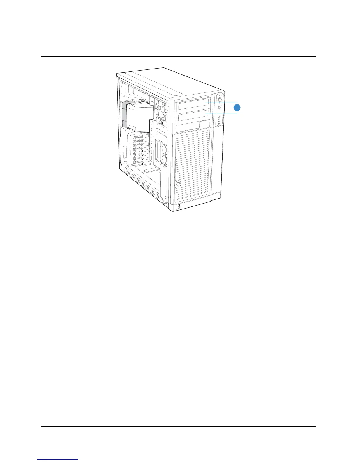
TP02032
A
A. Hard Disk Drive Bay
Figure 22. Drive Bay Locations for Intel
®
Entry Server Chassis SC5299-E (DP/WS/BRP
configuration shown)
4.1 3.5-in Peripheral Drive Bay
The Intel
®
Entry Server Chassis SC5299-E supports one 3.5-in removable media peripheral,
such as a floppy or tape drive, below the 5.25-in peripheral bays. The bezel must be removed
prior to 3.5-in removable media installation. When a drive is not installed, a snap-in EMI shield
must be in place to ensure regulatory compliance. A cosmetic plastic filler is provided to snap
into the bezel.
The 3.5-in bay is designed for tool-less insertion and removal so that no screws are required.
On the right side of the chassis, two protrusions in the sheet metal help locate the drive. On the
left side are two levers to lock the drive into place.
4.2 5.25-in Peripheral Drive Bays
The Intel
®
Entry Server Chassis SC5299-E supports two half-height 5.25-in removable media
peripheral devices, such as a magnetic/optical disk, CD-ROM drive, or tape drive. These
peripherals can be up to 9 inches (228.6 mm) deep on the non-redundant power chassis. The
650-W redundant power supply is longer in length and will limit the drives to approximately 7.5-
in maximum length. As a guideline, the maximum recommended power per device is 17W.