Standard Control Panel Intel
®
Entry Server Chassis SC5299-E TPS
Revision 3.1
Intel order number D37594-005
120
5. Standard Control Panel
The Intel
®
Entry Server Chassis SC5299-E control panel configuration has a three-button, five-
LED control panel.
When the hot-swap drive bay is installed, a bi-color hard drive LED is located on each drive
carrier (totally six) to indicate specific drive failure or activity. These LEDs are visible upon
opening the front bezel door.
5.1 Control Panel
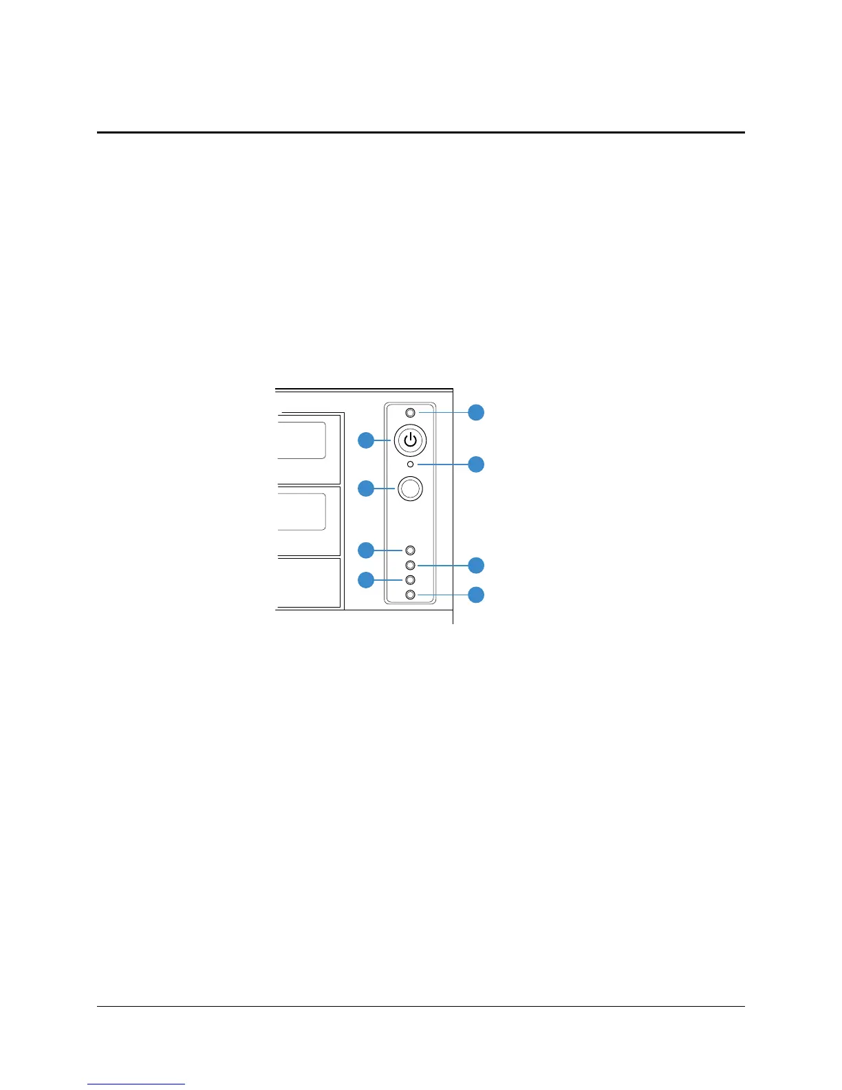
The control panel buttons and LED indicators are displayed in the following figure. The Entry
Ebay SSI (rev 3.61) compliant front panel header for Intel
®
server boards is located on the back
of the front panel. This allows for connection of a 24-pin ribbon cable for use with SSI rev 3.61-
compliant server boards. The connector cable is compatible with the 24-pin SSI standard.
TP00872
A
C
F
H
B
D
E
G
A. Power/Sleep LED
B. Power button
C. NMI button
D. Reset Button
E. LAN # 1 Activity LED
F. LAN # 2 Activity LED
G. Hard Drive Activity LED
H. Status LED
Figure 27. Panel Controls and Indicators