Intel
®
Entry Server Chassis SC5299-E TPS Peripheral and Hard Drive Support
Revision 3.1
Intel order number D37594-005
117
4.3.2.9 Clock Generation and Distribution
The 6HDD SATA HSBP provides one clock source. A 20-MHz oscillator provides the clock to
the GEM424 controller.
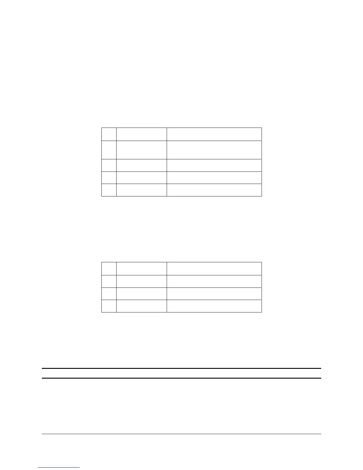
4.3.2.10 IPMB Header - IPMB
The following table defines the pin-out of the 4-pin IPMB Header (J13).
Table 136. IPMB Header Pin-out
Pin Signal Name Description
1 I
2
C Address
Control
IPMI interface address selection.
Primary = 0xC0, Secondary = 0xC2
2 BP_I2C_SCL Clock
3 GND
4 BP_I2C_SDA Data
4.3.2.11 SATA Host I
2
C Header - I2C_1
The following table defines the pin-out of the 3-pin SATA Host I
2
C Header (JP1).
Table 137. SATA Host I
2
C Header Pin-out
Pin Signal Name Description
1 BP_I2C_SDA Data
2 GND
3 BP_I2C_SCL Clock
4.3.2.12 Board Layout
The following figure shows the board layout and connector placement of the SATA hot-swap
backplane.
Note: Secondary side is mirrored.