Техника безопасности и рабочие функции
Обработка «голого» диска: OPTIMA
.
биения
подгонки.
OPTIMA FULL DIAGNOSTIC
(ОПТИМАЛЬНЫЙ С ПОЛНОЙ ДИАГНОСТИКОЙ)
1-6.
OPTIMA.
,
,
.
Control of the rim only: in OPTIMA mode, clamping
only the rim on the balancer, the laser scanner detects
the absence of the tire. In this condition, the rear laser
analyses the runout on the bead recess in the internal
part of the rim and will prompt to automatically proceed
with the matching.
OPTIMA FULL DIAGNOSTIC Mode
Identified by the symbol shown in figure 1-6. In this mode
the balancer performs the detailed diagnosis of the tyre,
as well as the OPTIMA mode functions.
A three-dimensional reconstruction of the wheel on the
screen and the use of specific colours, allow the operator
to examine the uniformity and wear of the tyre, the
presence of any faults on the wheel, that are hard to detect
with the naked eye.
1.4 Устройство станка
Рис. 1-7
:
1.
. 4.1.
2.
. 4.2.
3.
4.
5.
6.
7.
8.
9.
10. (5 )
11.
Рис. 1-8
1. ON/OFF (./.)
2.
3.
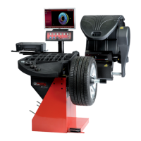
1.4 Layout
Figura 1-7
Nomenclature of the unit's parts:
1. Display
Refer to Chapter 4.1.
2. Input panel
Refer to Chapter 4.2.
3. Internal gauge arm
4. Flange
5. Stub shaft with hub nut
6. Weight compartments
7. Storage areas for cones and hub nuts
8. Wheel guard
9. Brake Pedal and Power Clamp Operation
10.Camera (5 Acquisition camera)
11. Laser Pointer
Figura 1-8
1. Mains switch (ON/OFF)
2. Power inlet
3. Main fuse