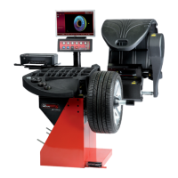
Балансировка и установка грузов
Balancing and weights Fitting
8.2 Установка балансировочных грузов
.
8.2.1 Установка пружинных грузиков
:
.
•
(3, Рис. 8-6).
•
.
•
(Рис. 8- 6).
:
( 4.1)
.
• .
ВНИМАНИЕ: ПРИ ПОДНЯТОМ КОЖУХЕ КОЛЕСО
ПРОДОЛЖАЕТ ВРАЩАТЬСЯ. УБЕДИТЕСЬ, ЧТОБЫ
КОЛЕСО НЕ БЫЛО БЛОКИРОВАНО
ИНСТРУМЕНТОМ ИЛИ ДРУГИМИ ПРЕДМЕТАМИ.
НОСИТЕ ЗАЩИТНЫЕ ОЧКИ И ПЛОТНО
ПРИЛЕГАЮЩУЮ ОДЕЖДУ.
•
.
•
.
•
(Рис. 8-6 и 8-7).
Примечание:
( 8.3).
8.2 Applying Balancing Weights
Fitting of balancing weights for the balancing modes is
specified and illustrated in this paragraph.
8.2.1 How to fit balance clips
Left correction plane:
After the mesuring run the wheel is braked such that the
weight for the left correction plane can be fitted exactly
perpendicular to and above the main shaft.
• If necessary, index the wheel precisely into the
correction position for the left plane. When the
correction position is reached, the two arrows (3, Fig.
8-6) light up green.
• Press the pedal of the main shaft lock to hold the
wheel in this position.
• Apply the clip on weight to the rim flange, in the
compensation position exactly perpendicular to and
above the wheel holder shaft (Figure 8- 6).
Righthand correction plane:
After the mesuring run (se4.1) the wheel is braked
such that the weight for the right correction plane can be
fitted exactly perpendicular to and above the main shaft.
• Release the brake pedal.
WARNING: THE WHEEL ROTATES WHEN THE
WHEEL GUARD IS OPEN. MAKE SURE THAT THE
WHEEL IS NOT BLOCKED BY TOOLS OR THE LIKE.
WEAR SAFETY GOGGLES AND TIGHTLY FITTING
WORKING CLOTHES.
• If necessary, turn the wheel again to move it into the
right correction plane compensation position.
• Press the pedal of the main shaft lock to hold the
wheel in this position.
• Apply the clip-on weight to the rim flange in the
correction position exactly perpendicular to and above
the wheel holder shaft (Figure 8-6 and 8-7).
After correction carry out a check run (see 8.3).
Note:
After balancing perform a Test Run (see Chapter 8.3).