Installation Instructions
iii Порядок установки.
Балансировочный станок:
i.
.
Кронштейны для хранения принадлежностей:
•
.
•
iii-1.
Приспособления зажима:
•
.
Механический зажим Power Clamp:
Рис. iii-2. 6.
Монитор:
Рис. iii-3. .
Рис. iii-2. VESA
(1a-1b) 5
.
(M4x10) VESA
.
Рис. iii-3.
.
.
iii Installation procedures.
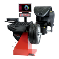
Wheel balancer:
Refer to the drawing in i for correct wheel balancer
positioning. If the wheel balancer needs securing, we
recommend fixing elements with a diameter of 8 mm,
quality 8.8 or higher.
Supports for Accessories:
Unpack the 4 threaded accessory support studs and
the support plates.
Refer to Figure iii-1. Fit the 4 threaded accessory support
studs and the plates.
Clamping devices:
Put the clamping devices on the accessory studs.
Power Clamp device:
Figure iii-2. Las instrucciones para la n se
hallan en el o 6.
Monitor:
Figure iii-3 Fitting the monitor
iii-2) The VESA support has three different fixing points,
which thanks to the two possible fitting positions (1a-1b)
provide 5 different possible fixing heights.
The 4 screws needed (M4x10) to fix the VESA support to
the monitor are part of the kit supplied.
iii-3) When fitting the monitor assembly you must choose
the appropriate fixing point.
The monitor assembly must be positioned in such a way
as to leave a minimum gap vertically between the monitor
and the keyboard support, allowing its angle to be
adjusted.