Installation Instructions
Крепление и подключение монитора
Рис. iii-4 (1, Рис. iii-4)
•
(2, Рис. iii-4)
.
•
1 (Рис. iii-4)
(3, Рис. iii-4).
ОСТОРОЖНО: УСТАНОВИТЕ ГЛАВНЫЙ
ВЫКЛЮЧАТЕЛЬ В ВЫКЛЮЧЕННОЕ ПОЛОЖЕНИЕ
ПЕРЕД ПОДКЛЮЧЕНИЕМ ЭЛЕКТРИЧЕСКИХ КАБЕЛЕЙ
Рис. iii-5
•
(1, Рис. iii6) .
•
(поз. 2),
(4, Рис. iii-4).
(3, Рис. iii-5).
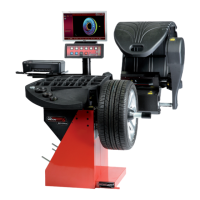
Fitting and connecting the monitor
Figure iii-4 Fitting the monitor support post (1, Fig. iii-4)
Run the connecting cables (2, Figure iii-4) into the
box.
Fix the column (1, Figure iii-4) to the back of the
box, by the two metal bands (3, Figure iii-4).
CAUTION: SET THE MAIN ON/OFF SWITCH TO THE
OFF POSITION BEFORE CONNECTING THE
ELECTRICAL CABLES
Figure iii-5 Connecting the monitor and the PC
•
Insert the monitor connector into the right-hand socket
(1, Fig. iii6) of the embedded PC unit.
•
Insert one end of the connecting lead from the
embedded PC to the electronic control of the wheel
balancer into the left-hand socket of the embedded PC
(item 2), and insert the other end into the socket close
to the main switch (4, Fig. iii-4).
A conventional external PC can be connected at the
centre socket (3, Figure iii-5)
iv Проверка.
•
0,25 (5 .) .
•
6.3.1).
v Инструктаж оператора.
(Данная информация предназначена только для
персонала службы технической поддержки)
•
.
•
.
•
.
•
.
iv Test procedures.
Balance a wheel to less than 0.25 oz. (5 grams) per
plane.
Perform a User Calibration. See Chapter 6.3.1.
v Instructing the operator.
(Following applies only if a unit is installed by a service
Technician)
Show and explain the Safety Booklet.
Show the operator how to switch the unit on and off.
Show the operator how to perform an emergency stop.
Show the operator how to select a wheel type, enter
data and apply a weight.