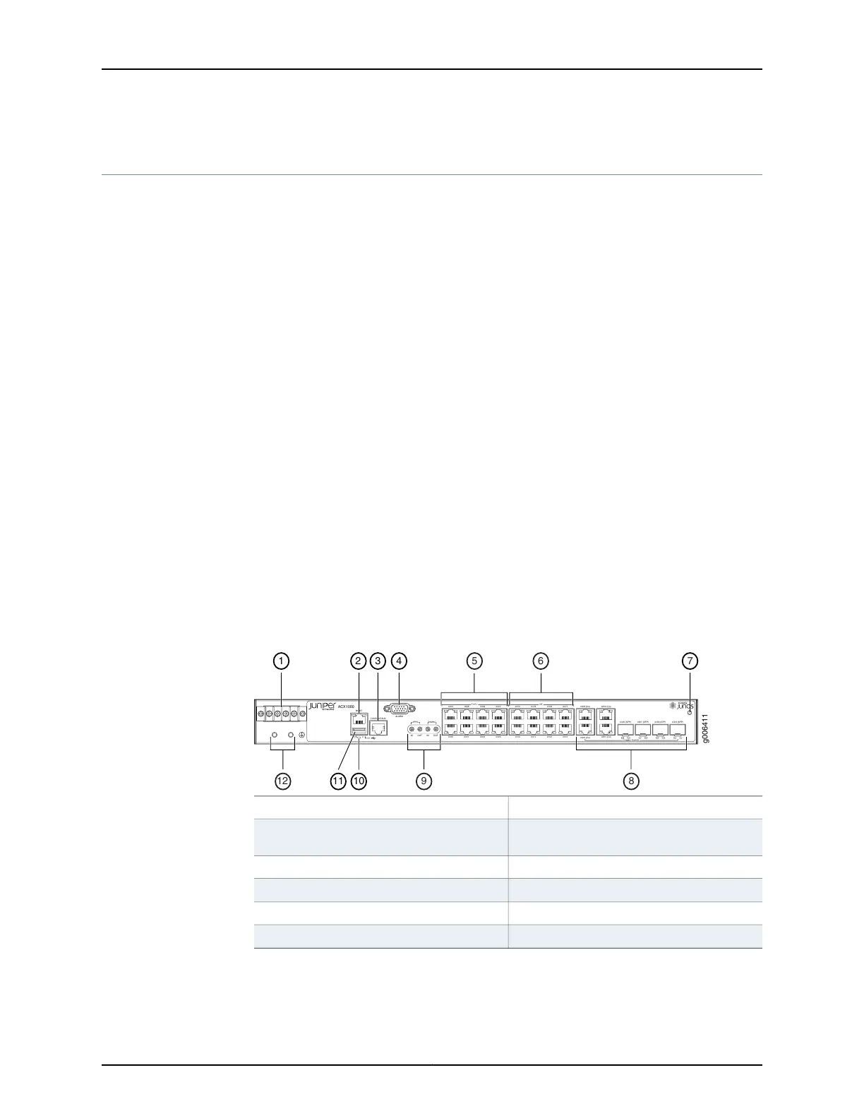
Front Panel of an ACX1000 Router
The front panel of an ACX1000 router consists of the following components (see
Figure 11 on page 30):
•
Chassis status LED labeled SYS
•
DC power terminals
•
USB port for upgrading Junos OS
•
Management Ethernet port labeled MGMT
•
Console or auxiliary port labeled CONSOLE/AUX
•
Alarm contact port labeled ALARM—accepts a DE-15 alarm cable
•
External clocking input port labeled EXT REF CLK IN
•
External clocking ports supporting 1PPS and 10MHz input and output
•
Network ports and corresponding status LEDs:
•
Eight T1/E1 ports labeled 0/0/0 through 0/0/7
•
Eight Gigabit Ethernet RJ-45 ports labeled 0/1/0 through 0/1/7
•
Combination Gigabit Ethernet ports labeled 0/2/0 through 0/2/3, either:
•
Four Gigabit Ethernet RJ-45 ports labeled Cu
•
Four Gigabit Ethernet ports labeled SFP that accept SFP transceivers
Figure 11: Front Panel of the ACX1000 Router
ACX1000
MGMT
SYS 0
CONSOLE/AUX
ALARM
1PPS
10MHz
IN
OUT
IN OUT
T1/E1
0/0/0
0/0/4
0/0/1
0/0/5
0/0/2
0/0/6
0/0/3
0/0/7
0/1/0
0/1/4
0/1/1
0/1/5
0/1/2
0/1/6
0/1/3
0/1/7
GE
0/2/0 (Cu)
0/2/2 (Cu)
0/2/1 (Cu)
0/2/3 (Cu)
0/2/0 (SFP)
0/2/1 (SFP) 0/2/2 (SFP) 0/2/3 (SFP)
COMBO PORTS
g006411
1 2 3 4
1011
5
6
7
9 812
7—1— ESD pointDC terminals
8—2— Combination Gigabit Ethernet RJ-45 and
SFP ports
Management Ethernet port
9—3— External clocking portsConsole or auxiliary port
10—4—
System (SYS) LED
Alarm contact port
11—5— USB portT1/E1 ports
12—6— Grounding terminals
Gigabit Ethernet (GE) ports
Related
Documentation
ACX1000 and ACX1100 Universal Access Router Overview on page 3•
Copyright © 2017, Juniper Networks, Inc.30
ACX1000 and ACX1100 Universal Access Router