CHAPTER 8
Planning Power Requirements
•
ACX1000 and ACX1100 Router Grounding Specifications on page 57
•
ACX1100 AC Power Specifications on page 59
•
ACX1100 AC Power Cord Specifications on page 59
•
ACX1000 and ACX1100 DC Power Specifications on page 61
ACX1000 and ACX1100 Router Grounding Specifications
•
Grounding Points Specifications on page 57
•
Grounding Cable Lug Specifications on page 58
•
Grounding Cable Specifications on page 59
Grounding Points Specifications
To meet safety and electromagnetic interference (EMI) requirements and to ensure
proper operation, the router must be adequately grounded before power is connected.
To ground ACX Series routers, you must connect a grounding cable to earth ground and
then attach it to the chassis grounding points using two paint-piercing washers and two
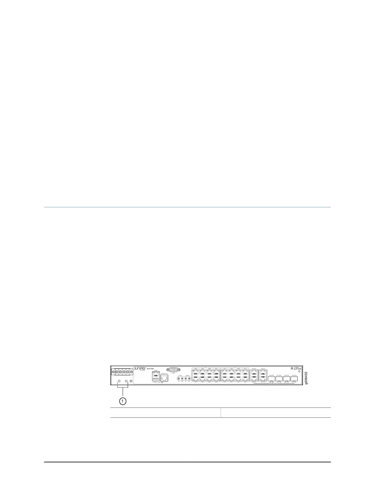
screws (not provided) (see Figure 17 on page 57).
Two threaded holes are provided on the front of the router chassis for connecting the
router to earth ground. The grounding points fit 0.5-inch-long SAE 10-32 screws
(American). The grounding points are spaced at 0.625-in. (15.86-mm) centers.
Figure 17: Grounding Points on the ACX1000 and ACX1100 Router
ACX1000
MGMT
SYS 0
CONSOLE/AUX
ALARM
1PPS
10MHz
IN OUT
IN OUT
T1/E1
0/0/0
0/0/4
0/0/1
0/0/5
0/0/2
0/0/6
0/0/3
0/0/7
0/1/0
0/1/4
0/1/1
0/1/5
0/1/2
0/1/6
0/1/3
0/1/7
GE
0/2/0 (Cu)
0/2/2 (Cu)
0/2/1 (Cu)
0/2/3 (Cu)
0/2/0 (SFP)
0/2/1 (SFP) 0/2/2 (SFP) 0/2/3 (SFP)
COMBO PORTS
g006432
1
1— Grounding points
57Copyright © 2017, Juniper Networks, Inc.