Power Supply (PEM) LEDs
Each power supply has two LEDs on the cra interface that indicate its status. The LEDs—labeled 0
through 3—are located on the cra interface next to the PEM label. Table 9 on page 33 describes the
funcons of the power supply LEDs on the cra interface.
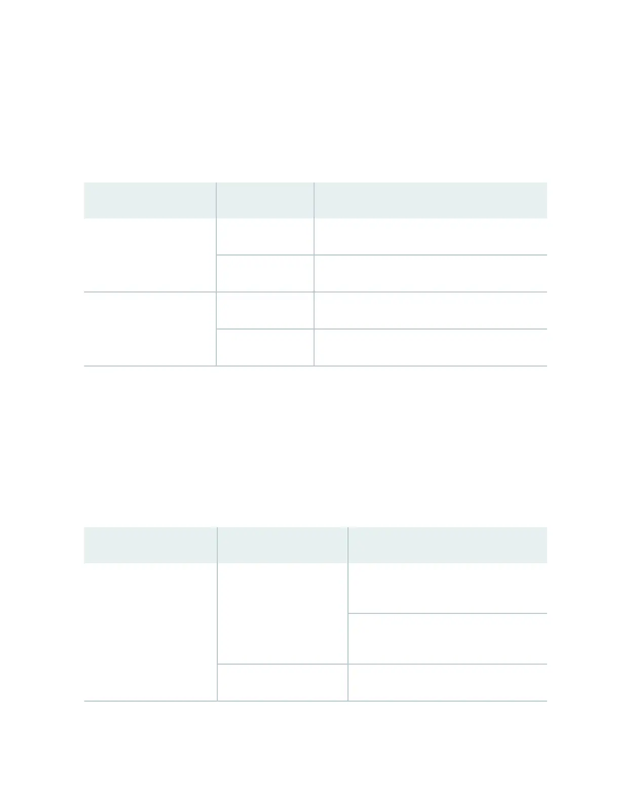
Table 9: Power Supply LEDs on the Cra Interface
Label Status Descripon
OK Green Power supply is funconing normally.
O Power supply in not installed.
FAIL Red Power supply has failed.
O Power supply is not installed or funconing normally.
Switch Fabric LEDs and Control Buons
Each Switch Fabric module has two LEDs on the cra interface that indicates its status. The LEDs—OK
and FAIL—are associated with control buons and are located along the boom of the cra interface.
You can turn the SF modules on or o by pressing these buons on the cra interface.
Table 10 on page 33 describes the status of the SF module LEDs.
Table 10: Switch Fabric Module LEDs on the
Cra Interface
Label Status Descripon
OK Green On steadily—The SF module is funconing
normally.
Blinking—The SF module is coming online or
going oine.
Unlit The SF module is not online.
33