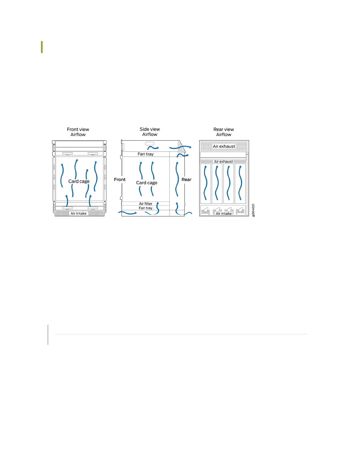
Airow Direcon in the EX9214 Switch Chassis
The air intake to cool the chassis is located on the front of the chassis, below the lower fan tray. Air is
pulled through the chassis toward the fan tray, pushed up through the line card slots, and through the
upper fan tray. See Figure 17 on page 42.
Figure 17: Airow Through the EX9214 Switch Chassis
The host subsystem monitors the temperature of switch components. Under normal operang
condions, the fans in the fan tray run at less than full speed. If a fan fails or the ambient temperature
rises above the threshold, the speed of the remaining fans is automacally adjusted to keep the
temperature within the acceptable range. If the ambient maximum temperature specicaon is
exceeded and the system cannot be adequately cooled, the Roung Engine shuts down the system by
disabling output power from each power supply.
You cannot replace a single fan. If one or more fans fail, you must replace the enre fan tray.
RELATED DOCUMENTATION
Clearance Requirements for Airow and Hardware Maintenance for an EX9214 Switch | 128
Installing a Fan Tray in an EX9200 Switch
42