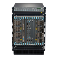
• MGMT port—Connects the EX9200-RE2 module through an Ethernet connecon to a management
LAN (or any other device that plugs into an Ethernet connecon) for out-of-band management. See
Connecng an EX9200 Switch to a Network for Out-of-Band Management
.
• Status LEDs—Indicate the status of the EX9200-RE2 module. Each EX9200-RE2 module has ve
LEDs labeled MASTER, ONLINE, OK/FAIL, DISK1, and DISK2 on the faceplate.
• ONLINE/OFFLINE buon—Turns the EX9200-RE2 module online or oine when pressed.
• USB1 and USB2 ports—Host a removable media interface using which you can install the Junos OS
manually. See
USB Port Specicaons for an EX Series Switch
.
• SSD 1 and SSD 2 slots—Host primary storage for soware images, conguraon les, and microcode.
Also provide secondary storage for log les and memory dump les.
• RESET buon—Reboots the EX9200-RE2 module when pressed.
• Capve screws—Secure the EX9200-RE2 module in place.
For the specicaons of the Roung Engine modules, see Table 21 on page 64.
Table 21: Roung Engine Module Specicaons
RE Module Processor Memory Connec
on to
Packet
Forwardin
g Engines
Disk Media First Junos
OS
Release
EX9200-RE RE-S-
EX9200-1800X4
(4 cores, 1.73 GHz)
16 GB Gigabit
Ethernet
32- GB hard
disk
4- GB
CompactFlash
card
12.3R2
EX9200-RE2 RE-S-
EX9200-2X00x6
(6 cores, 2 GHz)
64 GB Gigabit
Ethernet
50- GB SSD
X 2
No ash
memory
17.1R1
64

 Loading...