• ETHERNET port—Connects the EX9200-RE module through an Ethernet connecon to a
management LAN (or any other device that plugs into an Ethernet connecon) for out-of-band
management. See
Connecng an EX9200 Switch to a Network for Out-of-Band Management
.
• USB port—Hosts a removable media interface through which you can install the Junos OS manually.
See
USB Port Specicaons for an EX Series Switch
.
• SATA SSD 1 and SATA SSD 2 slots—Host primary storage for soware images, conguraon les,
and microcode. Also provide secondary storage for log les and memory dump les.
• RESET buon—Reboots the EX9200-RE module when pressed.
• ONLINE/OFFLINE buon—Turns the EX9200-RE module online or oine when pressed.
• Status LEDs—Indicate the status of the EX9200-RE module. Each EX9200-RE module has four LEDs
labeled MASTER, STORAGE, ONLINE, and OK/FAIL on the faceplate.
• Capve screws—Secure the EX9200-RE module in place.
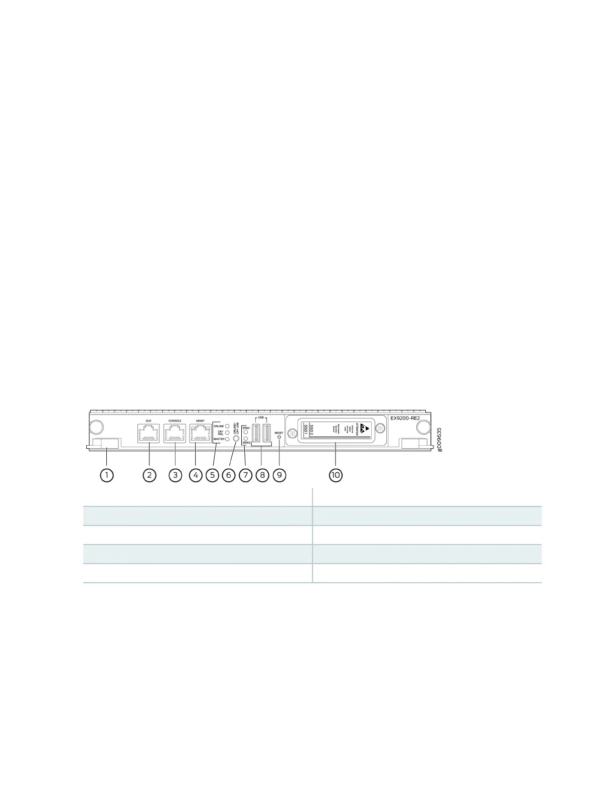
Figure 22 on page 63 shows the EX9200-RE2 module in an EX9200 switch.
Figure 22: EX9200-RE2 Module in an EX9200 Switch
1—
Extractor clips
6—
ONLINE/OFFLINE buon
2—
Auxiliary port (AUX)
7—
SSD LEDs—DISK1 and DISK2
3—
Console port (CONSOLE)
8—
USB ports—USB1 and USB2
4—
Management port (MGMT)
9—
RESET buon
5—
LEDs—ONLINE, OK/FAIL, and MASTER
10—
SSD slots—SSD 1 and SSD 2
Each EX9200-RE2 module consists of the following components:
• Extractor clips—Control the locking system to securely install and remove the EX9200-RE2 module.
• AUX port—Connects the EX9200-RE2 module to a modem or other auxiliary device.
• CONSOLE port—Connects the EX9200-RE2 module to a system console through a cable with an
RJ-45 connector. See
Connecng an EX9200 Switch to a Management Console or an Auxiliary
Device
.
63