ULTRAFLOW®54(H)/(J)
KamstrupA/S∙TechnicalDescription∙5512‐1554_J1_GB_04.2018
35
7.7 Installation examples (electrical)
7.7.1 Example of connection of ULTRAFLOW
®
and MULTICAL
®
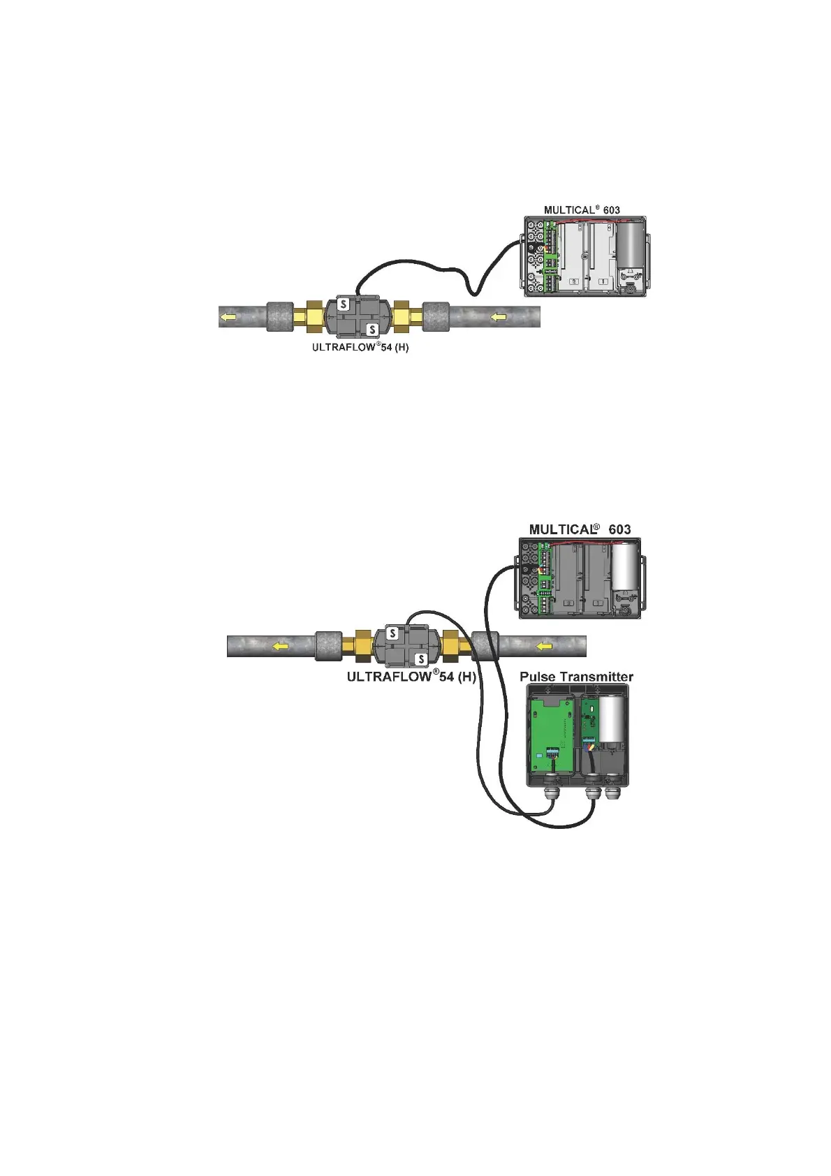
Figure 29. ULTRAFLOW
®
54 (H) connected to MULTICAL
®
603.
See paragraph 7.6 for electrical wiring.
7.7.2 Example of connection of Pulse Transmitter
Figure 30. ULTRAFLOW
®
54 (H) connected to battery supplied Pulse Transmitter.
MULTICAL
®
603 is connected to the Pulse Transmitter's output module (Y=3).
Note: If battery supplied, the right cable connection of the Pulse Transmitter is plugged.
 Loading...


