ULTRAFLOW®54(H)/(J)
KamstrupA/S∙TechnicalDescription∙5512‐1554_J1_GB_04.2018
19
6 Pressure loss
Pressure loss in a flow sensor is stated as max. pressure loss at q
p
. According to EN 1434, max. pressure loss must
not exceed 0.25 bar, unless the energy meter includes a flow controller or functions as pressure reducing
equipment.
The pressure loss in a sensor increases with the square of the flow and is usually stated as a direct proportionality
between the flow and the square root of the pressure loss:
pkqq
k
p
v
v
2
2
1
where:
q
= volume flow rate
h
m
3
v
k
= volume flow rate at 1 bar pressure loss
barh
m
3
p
= pressure loss
;bar
Pabar
5
101
q
p
Nom. diameter Δp@q
p
q@0.25 bar
[m³/h] [mm] [bar] [m³/h]
A 0.6 DN15/DN20 0.03 3.46
1.7
B 1.5 DN15/DN20 0.09
4.89
2.4
C 2.5 DN20 0.09
8.15
4.1
D 3,5 DN25 0.07
13.42
6.8
D 6 DN25* 0.20 13.42 6.8
E 6 DN25/DN32 0.06
24.50
12.3
F 10 DN40 0.06 40.83 20.4
* Types 65-5-CHJ6-XXX and 65-5-CHJ7-XXX.
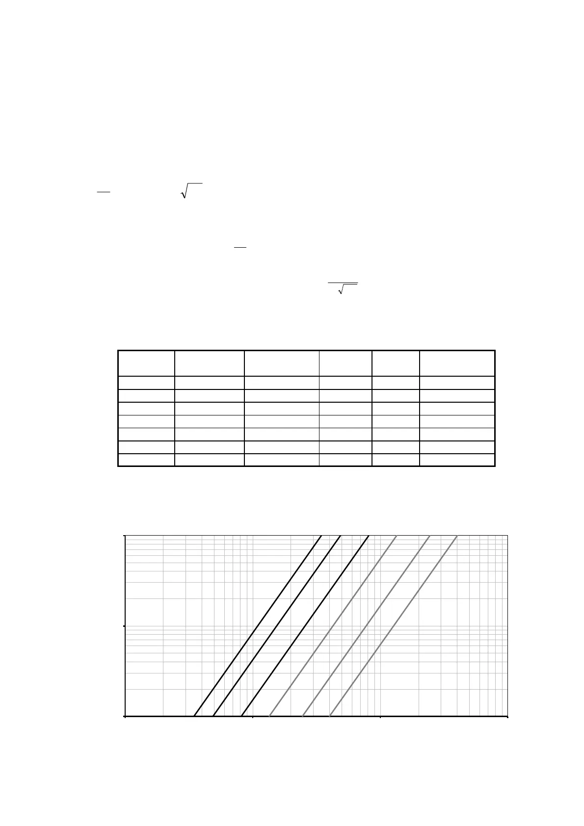
Graph kv
Table 11. Pressure loss table.
0,01
0,1
1
0,1 1 10 100
Δp [bar]
Flow [m³/h]
Δp ULTRAFLOW
®
54 (H)/(J)
AB
C
D
E
F
Figure 8. Pressure loss graphs of ULTRAFLOW
®
54 (H)/(J).
 Loading...


