ULTRAFLOW®54(H)/(J)
38
KamstrupA/S∙TechnicalDescription∙5512‐1554_J1_GB_04.2018
8 Functional description
Within the field of heat, cooling and water meters manufacturers have been working on alternative techniques to
replace flow sensors based on the mechanical principle. Research and development at Kamstrup has proven that
ultrasonic measuring is the most viable solution. Combined with microprocessor technology and piezo ceramics,
ultrasonic measuring is not only accurate but also reliable.
8.1 Flow measuring with ultrasound
Within ultrasonic flow measuring there are two main principles: the transit time method and the Doppler method.
The Doppler method is based on the frequency change, which occurs when sound is reflected by a moving particle.
You experience this effect when a car drives by. The sound (the frequency) decreases when the car passes by. The
transient time method used in ULTRAFLOW
®
utilizes the fact that it takes an ultrasonic signal emitted in the opposite
direction of the flow longer to travel from sender to receiver than a signal sent in the same direction as the flow.
A piezo ceramic element is used for transmitting and receiving ultrasound. The thickness of the element changes
when exposed to an electric field (voltage) and thereby it functions as a transmitter of ultrasound. When the element
is mechanically influenced, it generates a corresponding electric voltage, and thus functions as a receiver of
ultrasound.
8.2 Signal path, flow calculation and flow profiles
As it is outlined by the calculations below, the average flow velocity is directly proportional with the transit time
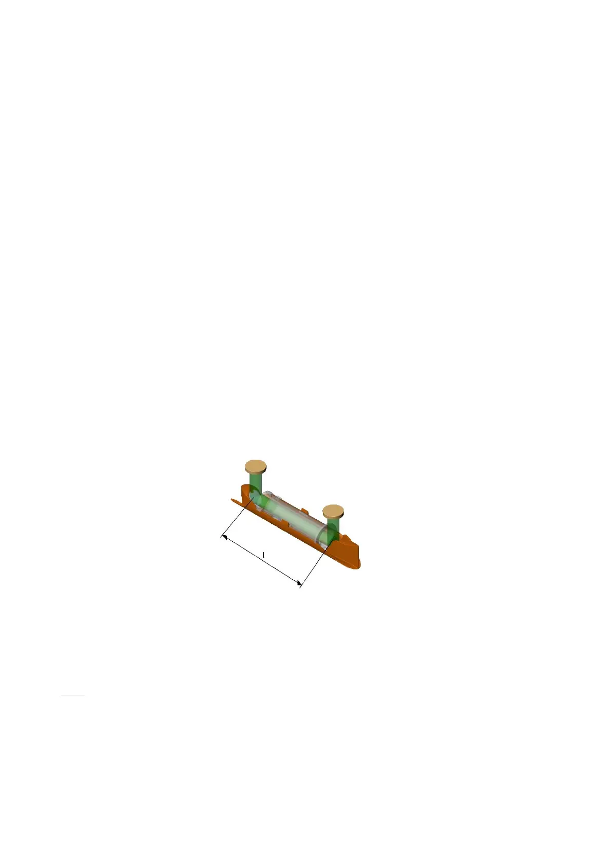
difference of ultrasound signals, which are sent with or against the flow. Figure 34 shows the main elements of the
signal path inside ULTRAFLOW
®
54 (H): Piezo-electric elements transmit and receive the ultrasound signal, which
is reflected into and through the measuring tube to the receiver via reflectors. Due to superposition of velocities of
water and sound signal, ultrasound spreads faster with the flow than against the flow.
Figure 34. Signal path inside ULTRAFLOW
®
54 (H) (q
p
0.6…2.5 m
3
/h). Sound signals are transmitted by the
transducers via 2 reflectors. The signal's transit times with and against the flow vary for the significant sound path
distance (parallel with the measuring tube). The flow is in this case from right to left.
For the calculation of the transit time difference, the signal path along the flow is crucial, and the transit time to the
measuring distance is calculated as:
vc
l
t
where:
is the transit time from sender to receiver of the sound signal along the measuring distance l [s]
l
is the measuring distance [m]
c
is the sound propagation velocity in stagnant water [m/s]

 Loading...


