ULTRAFLOW®54(H)/(J)
KamstrupA/S∙TechnicalDescription∙5512‐1554_J1_GB_04.2018
29
7.6 Electrical connections
7.6.1 Electrical connection of ULTRAFLOW
®
and MULTICAL
®
ULTRAFLOW
®
MULTICAL
®
Blue (ground)
11
Red (supply)
9
Yellow (signal)
10
Table 12. Connection of ULTRAFLOW
®
and MULTICAL
®
.
Using long control cables careful consideration is required in connection with installation. With a view to EMC there
must be a distance of min. 25 cm between control cables and all other cables.
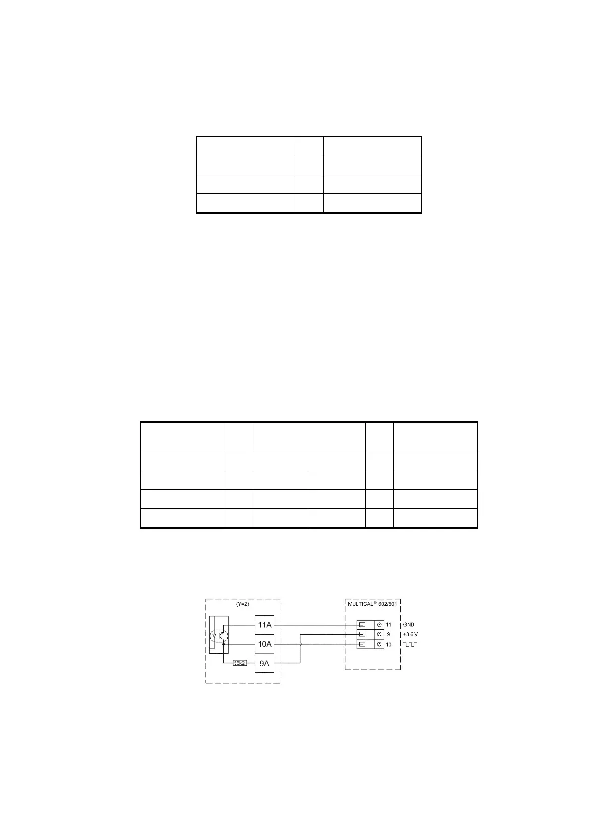
7.6.2 Electrical connection of Pulse Transmitter and Pulse Divider
If ULTRAFLOW
®
and MULTICAL
®
are connected via a Pulse Transmitter, ULTRAFLOW
®
is galvanically separated from
MULTICAL
®
.
Note: Flow-info is not possible if Pulse Transmitter is used.
If ULTRAFLOW
®
is connected to other equipment than MULTICAL
®
, always connect ULTRAFLOW
®
via Pulse
Transmitter or Pulse Divider.
ULTRAFLOW
®
Pulse Transmitter/
Pulse Divider
*)
MULTICAL
®
Input Output
Blue (ground)
11 11A
11
Red (supply)
9 9A
9
Yellow (signal)
10 10A
10
Table 13. Connection of ULTRAFLOW
®
and MULTICAL
®
via Pulse Transmitter/Pulse Divider.
*)
Pulse Divider is not normally used together with MULTICAL
®
.
Figure 20. Three-wire connection of Pulse Transmitter with output module (Y=2)
to MULTICAL
®
602/801.

 Loading...


