ULTRAFLOW®54(H)/(J)
KamstrupA/S∙TechnicalDescription∙5512‐1554_J1_GB_04.2018
45
8.6 Pulse output of Pulse Transmitter and Pulse Divider
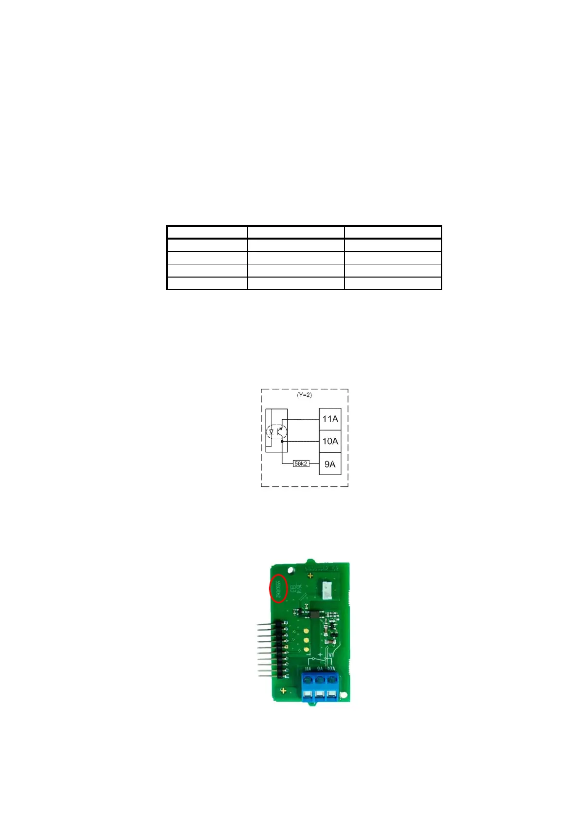
8.6.1 Galvanic separated output module (Y=2)
Pulse Transmitter/Pulse Divider is powered by the built-in supply module (Z=7 or 8).
Cable length to Pulse Transmitter/Pulse Divider depends on calculator.
To calculator:
Type: Open collector.
Connection: Two-wire or three-wire connection via the built-in 56.2 k pull-up.
Module Y=2 OC and OD (OB) Kam
Max input voltage 6 V 30 V
Max input current 0.1 mA 12 mA
ON condition U ≤ 0.3 V @ 0.1 mA
U
CE
≤ 2.5 V @ 12 mA
OFF condition R ≥ 6 MΩ R ≥ 6 MΩ
Table 15
Concerning meter factors and pulse duration see paragraph 4.3.4.
Figure 39. Block diagram for galvanic separated output module (Y=2).
Figure 40. Galvanic separated output module (Y=2). Note the PCB number 5550-1062
in the encircled area.

 Loading...


