ULTRAFLOW®54(H)/(J)
48
KamstrupA/S∙TechnicalDescription∙5512‐1554_J1_GB_04.2018
-6
-4
-2
0
2
4
6
0,0 1 0,1 1 10
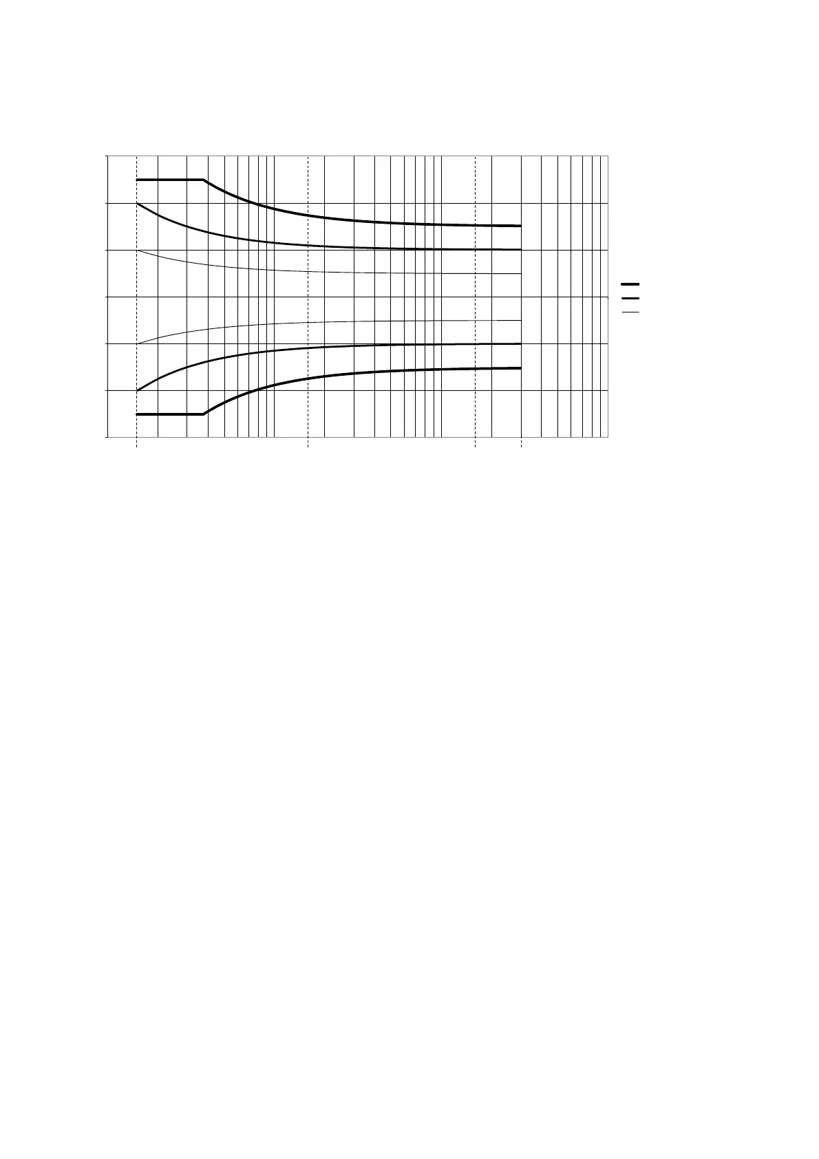
Tolerances [%]
Flow [m
3
/h]
Flow sensor tolerances q
i
:q
p
1:100 (q
p
1.5 m
3
/h)
EN1434 kl.3
EN1434 kl.2
½ EN1434 kl.2
q
s
q
p
0.1x q
p
q
i
Figure 43. Flow sensor tolerances q
i
:q
p
1:100 for q
p
1.5 m³/h.
8.9 Power consumption
The current consumption of ULTRAFLOW
®
is as follows:
Max. average 50 μA
Max. current 7 mA (max. 40 ms)
8.10 Interface connector/serial data
ULTRAFLOW
®
54 is fitted with a four-pole connector under the cover. Thus, it is not possible to access the connector
without breaking the seal. The cover is supplied with a factory seal, in connection with verified sensors it will be a
laboratory seal (legal seal).
The connector is used for:
Meter programming, including adjustment of flow charts by means of METERTOOL
Bringing the sensor into test mode
Reading accumulated water quantity in connection with calibration
External control of start/stop in connection with calibration
Due to different physical print layouts the interface connectors of the flow sensors q
p
0.6…2.5 m
3
/h (Type (H)) are
slightly different from the ones of the flow sensors q
p
≥ 3.5 m
3
/h (Type (J)). The interface connectors are constructed
as shown in Figure 44. Note, that the general function of the connectors is identical, but the positioning of single
functions is different.

 Loading...


