ULTRAFLOW®54(H)/(J)
50
KamstrupA/S∙TechnicalDescription∙5512‐1554_J1_GB_04.2018
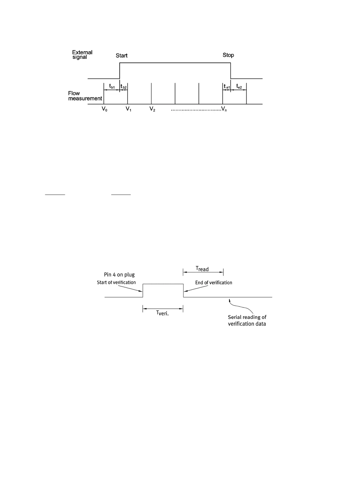
Figure 45
The excess quantity of water in connection with start is the water volume that passes through the sensor in the time
1b
t
before the first accumulation
1
V
within the test period. In the same way the lacking quantity is the water volume
passing through the sensor in the time
1e
t
after the last accumulation
n
V
until stop.
The volume accumulated during the test can be stated as:
n
ee
e
n
bb
b
Test
V
tt
t
VVV
tt
t
V
21
1
21
21
2
...
8.13 Calibration using serial data and externally controlled start/stop
The routine for calibrating ULTRAFLOW
®
using serial data is outlined below.
Figure 46
The sensor must be in test mode (see paragraph 8.11 Test mode).
Calibration is started by setting pin 4 of the internal connector on logical High (see Figure 46) and at the same time
starting the test in a flow stand. This might e.g. take place at the same time as the master meter starts accumulating
pulses or the diverter of the weighing system is changed. Now ULTRAFLOW
®
accumulates water volume until pin 4
is set to logical Low again to terminate the test. Subsequently, the volume accumulated during the test can be read
in consideration of start and stop. From the test has been completed and until the accumulated quantity of water
can be read, minimum 2 sec. must pass (T
read). Communication with ULTRAFLOW
®
during test is not allowed.
Pulse emission stops when pin 4 is on logical Low. The read water quantity and the number of emitted pulses may
differ as the pulse emission is monitored in intervals of 1 second.

 Loading...


