ULTRAFLOW®54(H)/(J)
52
KamstrupA/S∙TechnicalDescription∙5512‐1554_J1_GB_04.2018
9.2 Electrical Connection
Connection via three-wire cable from ULTRAFLOW
®
Yellow Signal
Red Supply
Blue Ground
Supply 3.6 VDC ± 0.1 VDC
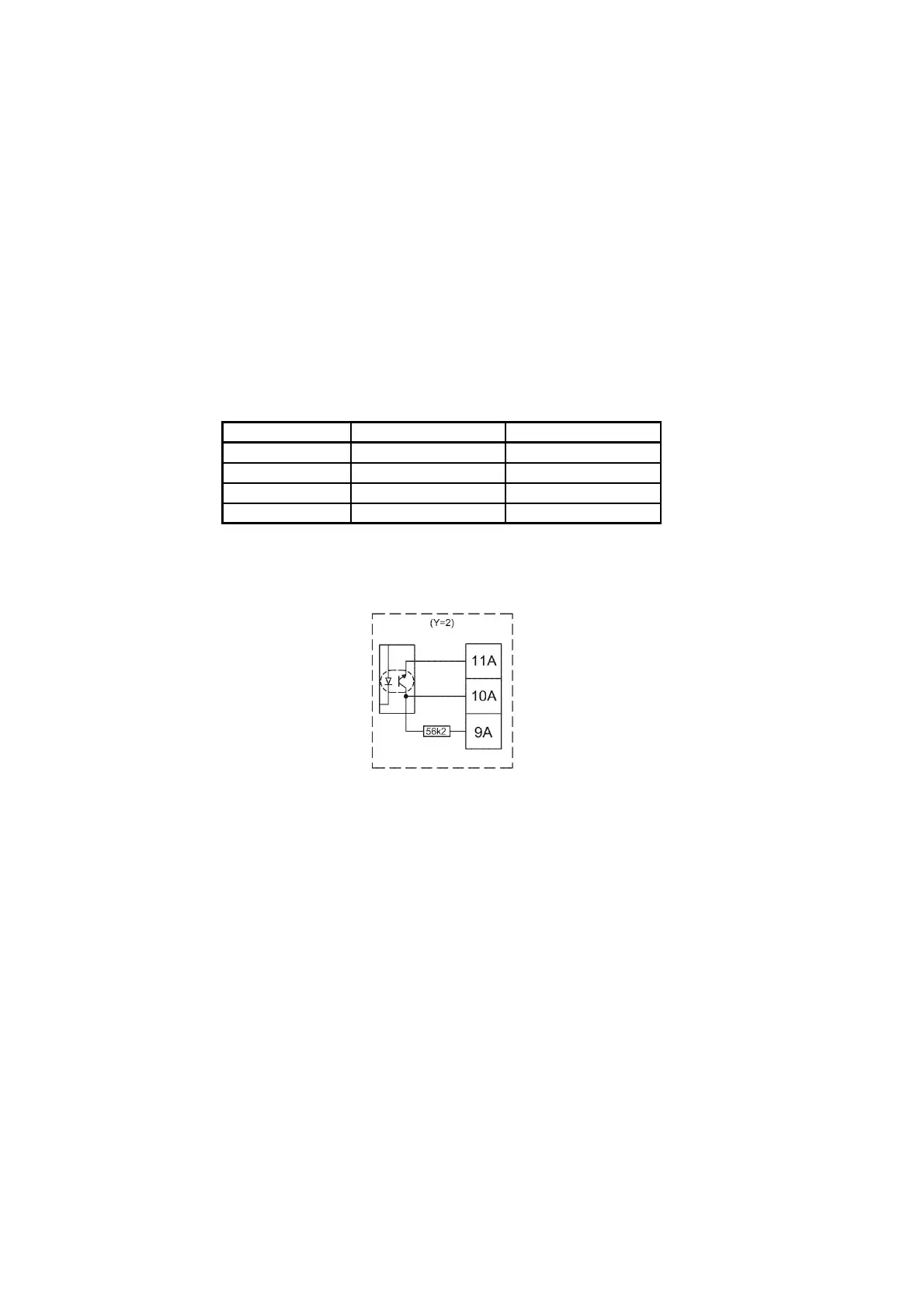
Output using Pulse Transmitter/Pulse Divider with galvanic separated output module (Y=2)
Type Open collector. Two-wire or three-wire connection is possible via the built-in 56.2 k pull-up
resistor.
Module Y=2 OC and OD (OB) Kam
Max. input voltage 6 V 30 V
Max. input current 0.1 mA 12 mA
ON condition U ≤ 0.3 V @ 0.1 mA
U
CE
≤ 2.5 V @ 12 mA
OFF condition R ≥ 6 MΩ R ≥ 6 MΩ
Table 18
Figure 48. Block diagram for galvanic separated output module (Y=2).
 Loading...


