ULTRAFLOW®54(H)/(J)
56
KamstrupA/S∙TechnicalDescription∙5512‐1554_J1_GB_04.2018
9.5 Pulse Tester
During a calibration process, it is often practical to use Pulse Tester type no. 6699-279, which has the following
functions:
Galvanic separated pulse outputs
Integral supply for ULTRAFLOW
LC-Display with counter
Externally controlled ”Hold” function
Can be mounted directly in a MULTICAL
connection base
9.5.1 Technical data of Pulse Tester
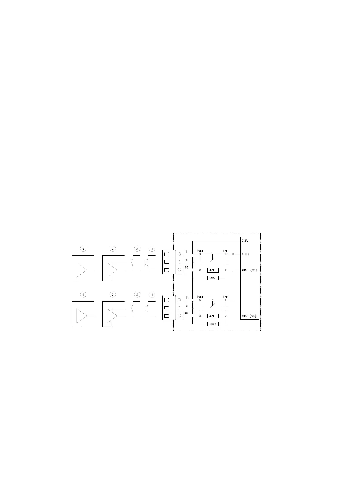
Pulse inputs (M1/M2)
Counter inputs Max. frequency: 128 Hz
Active signal Amplitude: 2.5 - 5 Vpp
Pulse duration 1 ms
Passive signal Internal pull-up 680 k
Internal supply 3.65 V lithium battery
Note: Depending on the connecting base used there are one or two pulse inputs/outputs.
Figure 50
1 Flow sensor with transistor output
The transmitter is normally an optocoupler with FET or transistor output to be connected to terminals 10 and
11 for flow sensor M1 and terminals 69 and 11 for flow sensor M2.
The leak current of the transistor must not exceed 1 A in OFF-state, and U
CE
in ON-state must not exceed 0.5
VDC.
 Loading...


