ULTRAFLOW®54(H)/(J)
KamstrupA/S∙TechnicalDescription∙5512‐1554_J1_GB_04.2018
57
2 Flow sensor with relay or reed switch output
The transmitter is a reed switch, which is normally mounted on vane wheel and Woltmann meters, or relay
output from e.g. MID-meters. This type of transmitter should not be used as the quick pulse input may cause
bounce problems.
3 Flow sensor with active pulse output, powered by Pulse Tester
This connection is used together with either Kamstrup's ULTRAFLOW
or Kamstrup's electronic pick-up for
vane wheel meters.
Connection (M1) 9: Red (9A) 10: Yellow (10A) 11: Blue (11A)
Connection (M2) 9: Red (9A) 69: Yellow (10A) 11: Blue (11A)
Table 22
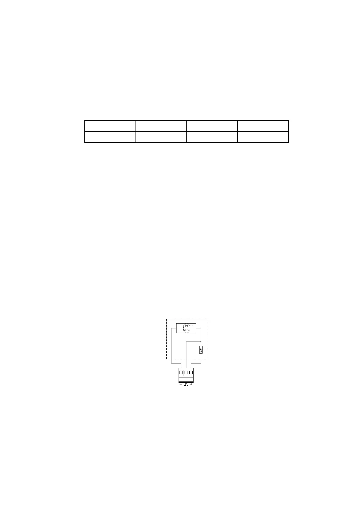
4 Flow sensor with active output and integral supply
Flow sensors with active signal output are connected as shown in Figure 51. The signal level must be
between 3.5 and 5 V. Higher signal levels can be connected via a passive voltage divider, e.g. of 47 k/10
k at a signal level of 24 V.
Pulse outputs (M1/M2)
Two-wire connection:
Voltage 24 V
Load 1.5 k
Three-wire connection:
Voltage 5...30 V
Load 5 k
Figure 51
The outputs are galvanic separated and protected against overvoltage and reversed polarity.
Max. counter capacity before overflow is 9,999,999 counts.

 Loading...


