ULTRAFLOW®54(H)/(J)
KamstrupA/S∙TechnicalDescription∙5512‐1554_J1_GB_04.2018
43
8.4 Guidelines for dimensioning ULTRAFLOW
®
In connection with installations it has proven practical to work with a back pressure (the pressure at the flow meter
outlet) of min. 1.0 bar (1.5 bar) at q
p
and min. 2.0 bar (2.5 bar) at q
s
for q
p
0.6…2.5 m
3
/h (q
p
≥ 3.5 m
3
/h) at
ULTRAFLOW
®
. This minimises the risk of measuring errors as a result of cavitation or air in the water.
It is not necessarily cavitation in the sensor itself, but also bubbles from cavitating pumps and regulating valves
mounted before the sensor. It can take some time until such bubbles have been dissolved in the water.
Furthermore, water can include air, which is dissolved in the water. The amount of air, which can be dissolved in
water, depends on pressure and temperature. This means that air bubbles can be formed due to falling pressure,
e.g. caused by a velocity rise in a contraction or above the sensor.
The risk of these factors affecting accuracy is reduced by maintaining a fair pressure in the system.
In relation to the recommended back pressure, the steam pressure at current temperature must also be considered.
The recommended back pressure applies to temperatures up to approx. 80°C. Furthermore, it must be taken into
account that the above-mentioned pressure is the back pressure at the sensor, which has typically been measured
as a static pressure, and that the pressure is lower after a contraction than before one (among other things cones).
This means that the pressure - when measured elsewhere - might be different from the pressure at the sensor.
This can be explained by combining Bernoulli’s equation and the continuity equation. Based on Bernoulli's
equation the total pressure of the flow will be the same for any cross section. It can be reduced to: P
stat.
+ P
dynam.
=
P
stat.
+ ½ν
= constant (P
stat.
= static pressure; P
dynam.
= dynamic pressure; = density of water; ν = flow velocity of
water). The continuity equation determines that the product of pipe cross sectional area
A
and average flow
velocity ν, which corresponds to the volume flow rate passing through, is constant for an incompressible fluid like
e.g. water. Therefore, the flow velocity is increased in a contraction and the static pressure falls.
Dimensioning a flow sensor you must take the above into consideration, especially if the sensor is used within the
scope of EN 1434 between q
p
and q
s
, and in case of major pipe contractions.
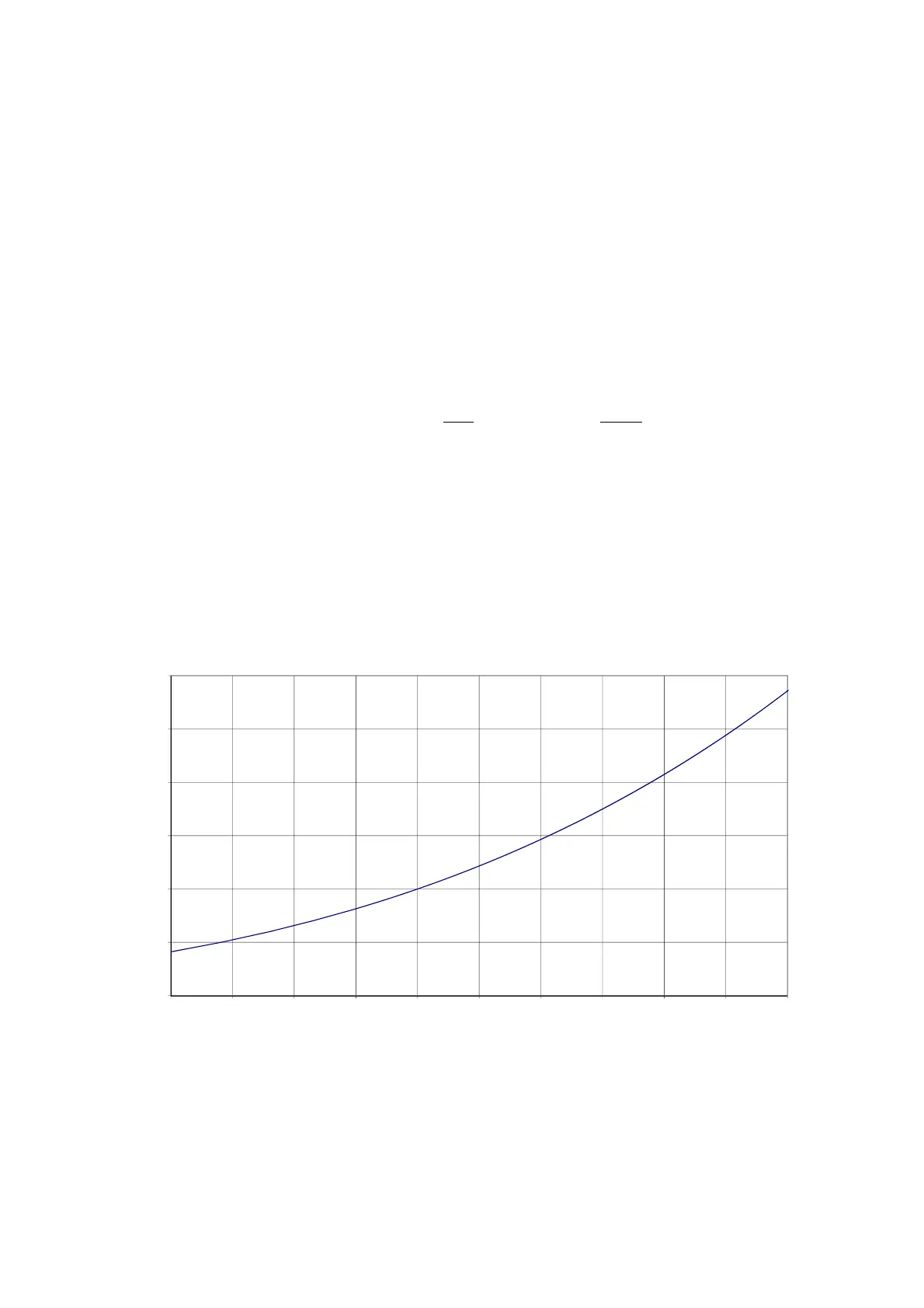
Figure 37. Steam pressure of water.
0
0,5
1
1,5
2
2,5
3
80 85 90 95 100 105 110 115 120 125 130
[bar]
[°C]
Steampressure
 Loading...


