162 Keysight E4981A 120 Hz/1 kHz/1 MHz Capacitance Meter
Using Scanner Interface
Electrical Characteristics
9-
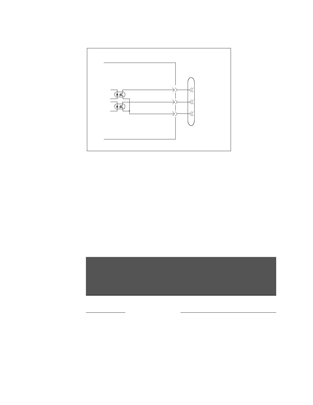
Figure 9-4 Circuit diagram of the scanner interface output signals
Input signal
Each input signal is connected to the cathode side of the photo coupler LED.
The anode side of the LED is connected to the drive source voltage.
Table 9-4 shows the electrical characteristics of the input signals. Figure 9-5
and Figure 9-6 show the circuit diagram of the input signals. The amount of
current flowing through the LED depends on the setups of the drive source
voltage, and the external trigger (EXT_TRIG) signal resistance setup switch (S1,
S2).
The S1, S2 switches belongs to electrical switches that can be control by the
following SCPi command :SYSTem:SCANner:TRIGger:VOLTage <para>
The current can be calculated by the following formula:
I = (DCV-Vf-Low)/R
Low = 0 V
EXT_TRIG Vf = 1.3 V (typical)
\CH0 -\CH7 \CH_VALID Vf = 1.1 V (typical)
e4981aue0045
COMMON
/INDEX
/EOM
Scanner
interface
connector
Interface Board (E4981-66537)
Table 9-4 Electrical characteristics of the scanner interface input signals
Input signal
Input voltage [V]
Input current (LOW) [mA] (typical)
Pull-up source voltage: EXT_DCV
LOW HIGH 5 V 9 V 15 V
/CH0 - /CH7,
/CH_VALID
0 - 1 EXT_DCV
4.8 13.3 17.0
EXT_TRIG 3.7 4.7 6.0