ENGLISH
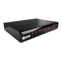
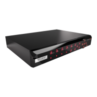
Chapter 1: Product Overview
14
DVR User’s Manual
16-Channel DVR
CH1
CH9
CH2
CH10
CH3
CH11
CH4
CH12
CH5
CH13
CH6
CH14
CH7
CH15
CH8
CH16
1
3
2
AUDIO
IN
4
VIDEO OUT
MAIN
VIDEO OUT
SPOT
AUDIO IN (CH5-CH16)
HDMI VGA
12V
LAN
G 12345678910 11
+
-
NO COM
G1615141312
RS-485 OUT
D
+
D
-
KB IN
ALARM
1
2
AUDIO
OUT
1 2 3 54 76 8 109
13 12 11
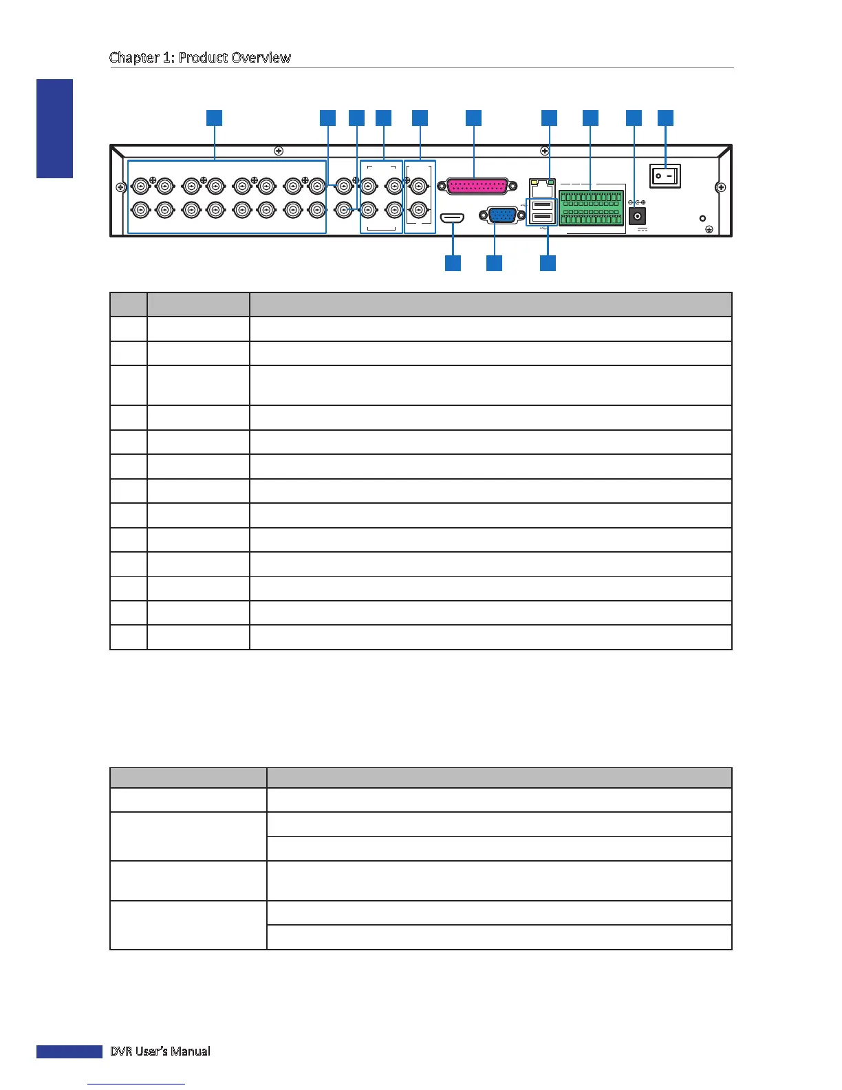
No. Connector Descripon
1 Video input Connects to a maximum of 16 video input devices via BNC.
2 Video output Connects to a video output device via BNC.
3
Video SPOT
output
Connects to a video output device via BNC wherein only channels with VIDEO OUTPUT
seng congured to SPOT-OUT are displayed.
4 Audio input Connects to a maximum of 4 audio input devices via BNC.
5 Audio output Connects to a maximum of 2 audio output devices via BNC.
6 Parallel input Connects to a maximum of 12 audio input using a Parallel-to-BNC adapter.
7 LAN Connects to LAN via RJ-45.
8 RS-485 Connects to a Speed dome camera, sensor or alarm device via RS-485.
9 Power Connects to the power adapter.
10 Power switch Press to turn the DVR on or o.
11 USB port Connects to a USB mouse, ash disk, and other external storage drive.
12 VGA output Connects to a VGA monitor.
13 HDMI output Connects to a monitor output via HDMI.
1.4 Mouse
The DVR is supplied with a USB mouse that you can use to operate the DVR. Simply plug in the supplied mouse into
the USB mouse connector at the rear panel of the device.
Mouse Operaon Descripon
Le-click In OSD menu, click the le buon to select and edit the seng.
Right-click In preview mode, click the right buon to display the pop-up menu.
In main menu or sub menu mode, click the right buon to exit the current menu.
Double-click the Le buon Double-click the live image of any channel for full screen display. Double-click the le
buon again to return to the window-display of all cameras.
Drag an area/line In moon mode, use this funcon to select moon area.
In [Color Setup] menu mode, it will adjust color control bar.