ENGLISH
Chapter 2: Installaon
22
DVR User’s Manual
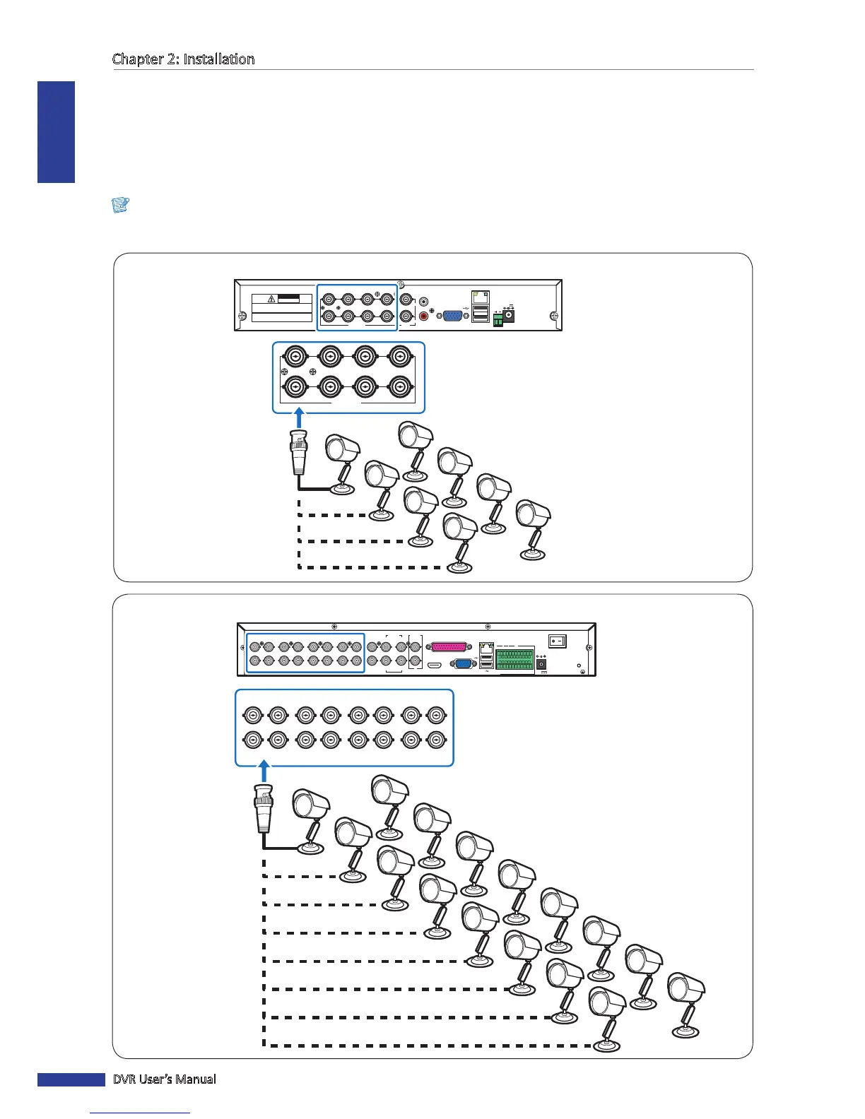
2.4 Connecng the Cameras
Connect the camera cable(s) to the video input of the DVR via BNC or RS-485 connecon.
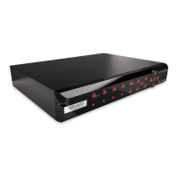
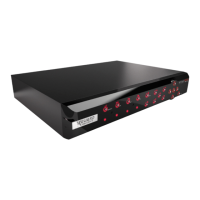
2.4.1 BNC Connecon
Connect the camera cable(s) to the video input of the DVR via BNC connector as shown.
Note:
The illustraon below is of an 8-channel DVR. For 4-channel DVRs, only four video input connecon via BNC are
available.
CH1
CH9
CH2
CH10
CH3
CH11
CH4
CH12
CH5
CH13
CH6
CH14
CH7
CH15
CH8
CH16
1
3
2
AUDIO
IN
4
VIDEO OUT
MAIN
VIDEO OUT
SPOT
AUDIO IN (CH5-CH16)
HDMI VGA
12V
LAN
G 12345678910 11
+
-
NO COM
G1615141312
RS-485 OUT
D
+
D
-
KB IN
ALARM
1
2
AUDIO
OUT
CH1
CH9
CH2
CH10
CH3
CH11
CH4
CH12
CH5
CH13
CH6
CH14
CH7
CH15
CH8
CH16
BNC cable
Camera
16-Channel DVR
RS-485
3
4
1
2
1
2
VIDEO
OUTPUT
7
8
5
6
VIDEO INPUT AUDIO
OUTPUT
AUDIO
INPUT
VGA
12V
LAN
CAUTION
RISK OF ELECTRIC SHOCK
DO NOT OPEN
CAUTION: TO REDUCE THE RISK OF ELECTRICAL SHOCK.
DO NOT OPEN COVERS. NO USER SERVICEABLE
PARTS INSIDE. REFER SERVICING TO QUALIFIED
SERVICE PERSONNEL.
WARNING: TO PREVENT FIRE OR SHOCK HAZARD. DO NOT
EXPOSE UNITS NOT SPECIFICALLY DESIGNED FOR
OUTDOOR USE TO RAIN OR MOISTURE.
3
4
1
2
7
8
5
6
VIDEO INPUT
4-Channel / 8-Channel DVR
BNC cable
Camera