ENGLISH
Chapter 2: Installaon
20
DVR User’s Manual
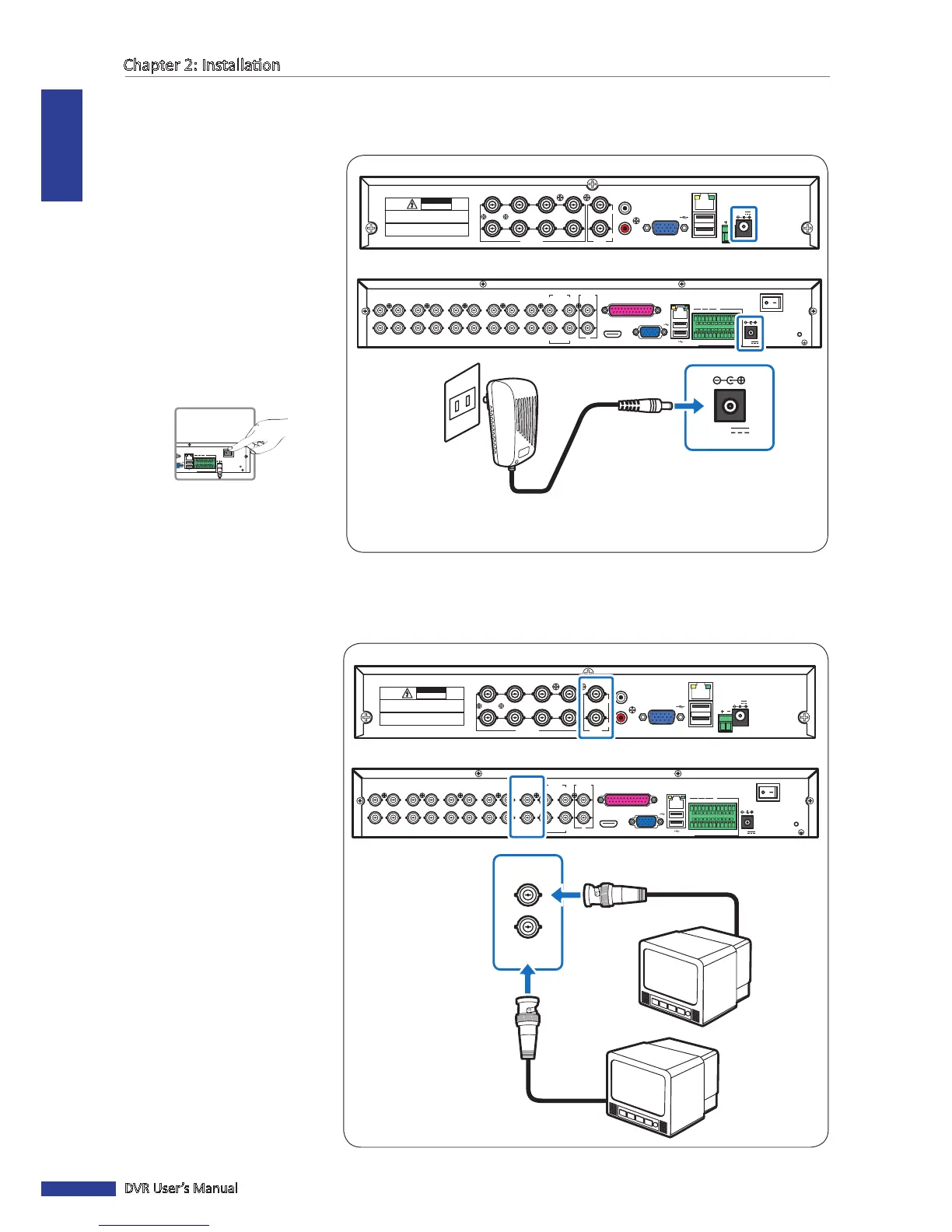
2.2 Connecng the Power
Use only the supplied power adapter that came with the DVR.
1 Connect one end of the power
adapter to the power connector
on the back of the DVR.
2 Plug the other end of the power
adapter into the wall outlet.
3 For 4-channel/8-channel
models, the DVR automacally
powers on.
For a 16-channel DVR, press
the Power switch to turn on the
power.
RS-485
3
4
1
2
1
2
VIDEO
OUTPUT
7
8
5
6
VIDEO INPUT AUDIO
OUTPUT
AUDIO
INPUT
VGA
12V
LAN
CAUTION
RISK OF ELECTRIC SHOCK
DO NOT OPEN
CAUTION: TO REDUCE THE RISK OF ELECTRICAL SHOCK.
DO NOT OPEN COVERS. NO USER SERVICEABLE
PARTS INSIDE. REFER SERVICING TO QUALIFIED
SERVICE PERSONNEL.
WARNING: TO PREVENT FIRE OR SHOCK HAZARD. DO NOT
EXPOSE UNITS NOT SPECIFICALLY DESIGNED FOR
OUTDOOR USE TO RAIN OR MOISTURE.
CH1
CH9
CH2
CH10
CH3
CH11
CH4
CH12
CH5
CH13
CH6
CH14
CH7
CH15
CH8
CH16
1
3
2
AUDIO
IN
4
VIDEO OUT
MAIN
VIDEO OUT
SPOT
AUDIO IN (CH5-CH16)
HDMI VGA
12V
LAN
G 12345678910 11
+
-
NO COM
G1615141312
RS-485 OUT
D
+
D
-
KB IN
ALARM
1
2
AUDIO
OUT
12V
Power adapter
Wall outlet
4-Channel DVR / 8-Channel DVR
16-Channel DVR
2.3 Connecng to Monitors
The preview screen can be displayed on monitors via BNC, VGA or HDMI (16-channel) connecon.
2.3.1 BNC Connecon
Connect the video output of
the DVR to the monitor via BNC
connector as shown.
RS-485
3
4
1
2
1
2
VIDEO
OUTPUT
7
8
5
6
VIDEO INPUT AUDIO
OUTPUT
AUDIO
INPUT
VGA
12V
LAN
CAUTION
RISK OF ELECTRIC SHOCK
DO NOT OPEN
CAUTION: TO REDUCE THE RISK OF ELECTRICAL SHOCK.
DO NOT OPEN COVERS. NO USER SERVICEABLE
PARTS INSIDE. REFER SERVICING TO QUALIFIED
SERVICE PERSONNEL.
WARNING: TO PREVENT FIRE OR SHOCK HAZARD. DO NOT
EXPOSE UNITS NOT SPECIFICALLY DESIGNED FOR
OUTDOOR USE TO RAIN OR MOISTURE.
CH1
CH9
CH2
CH10
CH3
CH11
CH4
CH12
CH5
CH13
CH6
CH14
CH7
CH15
CH8
CH16
1
3
2
AUDIO
IN
4
VIDEO OUT
MAIN
VIDEO OUT
SPOT
AUDIO IN (CH5-CH16)
HDMI VGA
12V
LAN
G 12345678910 11
+
-
NO COM
G1615141312
RS-485 OUT
D
+
D
-
KB IN
ALARM
1
2
AUDIO
OUT
VIDEO OUT
MAIN
VIDEO OUT
SPOT
Monitor
Monitor
BNC cable
BNC cable
4-Channel DVR / 8-Channel DVR
16-Channel DVR