DIAGNOSTICS Checkout Procedures
10DEC05
DG4825-1
Page
141 of 180
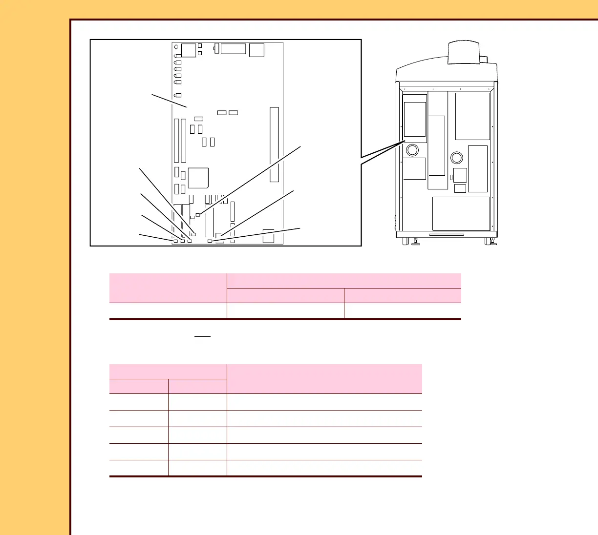
1 Check for correct voltages on CONNECTOR P5:
2 If the voltage is not correct, do the checkout for the POWER SUPPLY PS1.
3 Measure the following voltages at the indicated test points.
Voltage
MULTIMETER
Ground Positive
+24 V DC P5-3 or P5-4 P5-1 or P5-2
MULTIMETER
Voltage
Ground Positive
TP5 TP4 +3.3 ± 0.1 V DC, Linear
TP5 TP21 +3.3 ± 0.1 V DC, Analog
TP5 TP1 +5 ± 0.1 V DC
TP5 TP14 +12 ± 0.2 V DC
TP5 TP8 +24 ± 0.5 V DC
H194_0034BC
BOARD A2
PROCESSING
CENTRAL
MASTER
TP8
TP14
TP1
TP21
TP4
TP5
P5
CONNECTOR
H194_0034BCA
 Loading...


