Drive Chain
Adjustment of the Tension on the Drive Chain
[1] Check that the DRIVE CHAIN is wet with
solution.
[2] Check that the RACK ASSEMBLY is at
approximately the same temperature as the
solutions in the tanks, to assure that the
DRIVE CHAIN is the correct length.
[3] Loosen the 4 HOLDING SCREWS.
[4] Hold the RACK ASSEMBLY above the work
surface until gravity tightens the DRIVE
CHAIN around the TURNAROUND
ASSEMBLY.
[5] Rotate the DRIVE GEAR one full turn.
[6] Tighten the 2 HOLDING SCREWS on the
drive side first.
[7] Place the RACK ASSEMBLY on the work
surface.
[8] Rotate the ADJUSTING SCREWS until the
distance between the SIDE PLATE of the
RACK and the SIDE PLATE of the
TURNAROUND ASSEMBLY on the non-drive
side is equal to the distance between the
2 SIDE PLATES on the drive side.
[9] Tighten the 2 HOLDING SCREWS on the
non-drive side.
NOTE
Remove LINKS from the DRIVE
CHAIN if necessary to provide the
correct length. See steps 1 - 5.
H112_0109CA
H112_0109CCA
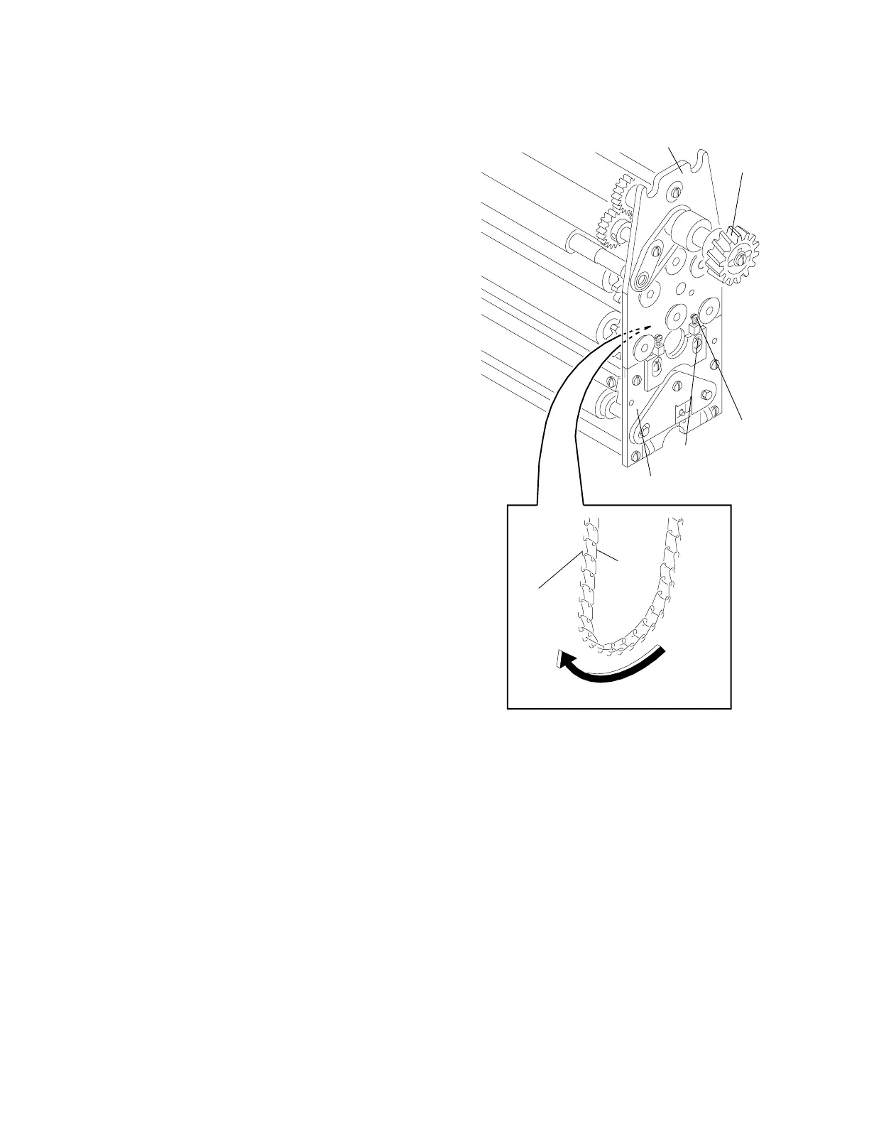
DRIVE CHAIN
HOOK
LINK
ASSEMBLY
TURNAROUND
SCREW (4)
HOLDING
SCREW (4)
ADJUSTING
GEAR
DRIVE
SIDE PLATE
Replacement of the Drive Chain
[1] To open the existing DRIVE CHAIN, insert a [3] Pull the existing DRIVE CHAIN through the
screwdriver under the HOOKS of a LINK. RACK ASSEMBLY until the new DRIVE
Rotate the screwdriver if necessary. CHAIN is in the correct position.
[2] Attach the new DRIVE CHAIN to the existing [4] Disconnect the existing DRIVE CHAIN from
DRIVE CHAIN with the HOOKS in the the new DRIVE CHAIN.
direction of travel and the openings of the
[5] Connect the ends of the new DRIVE CHAIN.
LINKS outward. See the illustration.
[6] Do the Drive Chain Adjustment above.
2-8 981777
 Loading...


