Diagrams
NOTE
If the processor does not operate correctly after checking through the table starting on page 4-1
of this Service Manual, see the diagrams in this section.
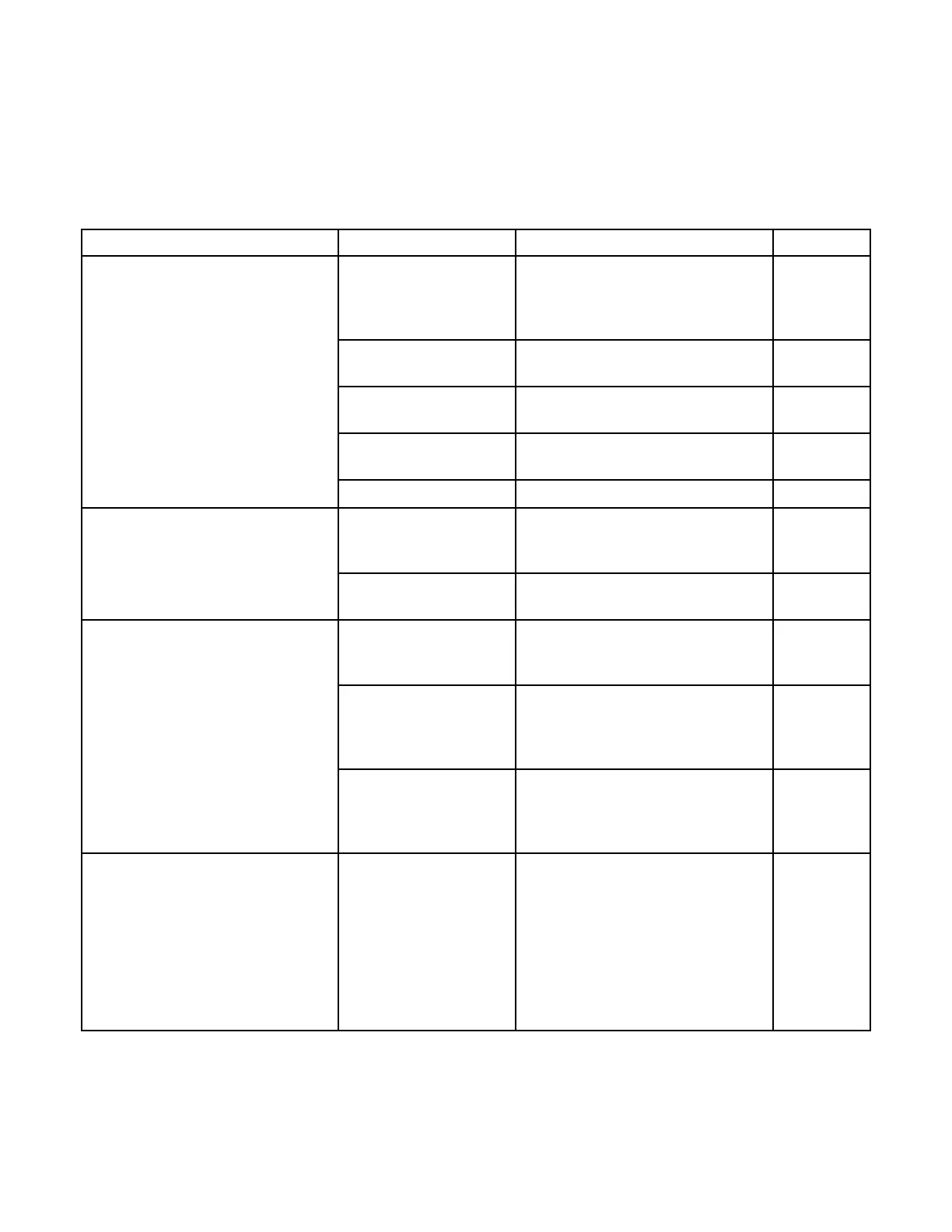
System Condition Description Figure
Dryer Temperature Control or Sequence of Operation 5-1
Main Drive Circuit Diagram, 800 Board 5-2
Circuit Diagram, M35 5-3
Circuit Diagram, M35A 5-4
No Blower Motor or Diagnostic Flowchart 5-5
Drive Motor
No Drive Motor or Circuit Board Flowchart, M35A 5-6
Dryer Heat
No Dryer Heat Diagnostic Flowchart, M35 5-7
Diagnostic Flowchart, M35A 5-8
No Blower Motor Diagnostic Flowchart 5-9
Replenishment Control System Sequence for Film Feeding 5-10
Circuit Diagram, M35 5-11
Circuit Diagram, M35A 5-12
No Replenishment Diagnostic Flowchart 5-13
Pump
Developer Temperature Sequence of Operation 5-14
Circuit Diagram, M35 5-15
Circuit Diagram, M35A 5-16
No Developer Heat Diagnostic Flowchart 5-17
and Temperature
Ready Light Is On
or Off
Developer Heat on All Diagnostic Flowchart 5-18
the Time and
Temperature Ready
Light Is On
Complete Processor Sequence of Operation 5-19
Circuit Diagram, M35 5-20
Circuit Diagram, M35A 5-21
Wiring Diagram, M35 5-22
Wiring Diagram, M35A 5-23
Wiring Diagram, M35 Control Box 5-24
Wiring Diagram, M35A Control
Box 5-25
Circuit Diagram, 100 Board 5-26
981777 5-1
 Loading...


