COMMON RAIL SYSTEM
07-CR-E5,07-CR-TE5,07-CR-TIE5, DM
1-S198
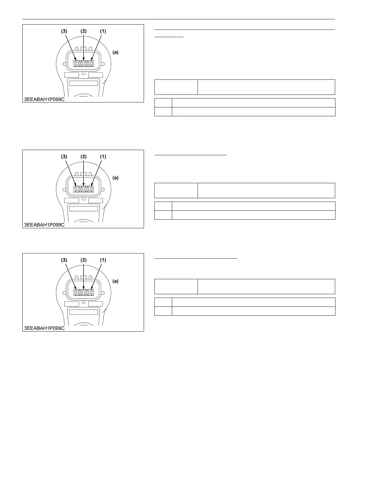
2. Check the Voltage Between Camshaft Position Sensor
Terminals
1. Place the key switch in the OFF position, and unplug the
camshaft position sensor connector from the socket.
2. Place the key switch in the ON position, and measure the
voltage between G-VCC and G-GND terminals at the wiring
harness side.
9Y3200007CRS0280US0
3. Check the Connectors
1. Check the sensor and wiring harness connectors for incorrect
connection, inappropriate fitting, poor contact or other faulty
areas.
9Y3200007CRS0281US0
4. Check the Wiring Harness
1. Check the wiring harness between G+ terminal of sensor and
engine ECU for a short or an open circuit.
9Y3200007CRS0282US0
Service
specification
Approx. 5 V
OK Go to "3. Check the Connectors".
NG Go to "5. Measure the Engine ECU Terminal Voltage".
(1) Terminal G+
(2) Terminal G-GND
(3) Terminal G-VCC
(a) Pin Assignment
Service
specification
Must be free from incorrect connection, inappropriate fitting,
poor contact.
OK Go to "4. Check the Wiring Harness".
NG Repair or replace.
(1) Terminal G+
(2) Terminal G-GND
(3) Terminal G-VCC
(a) Pin Assignment
Service
specification
Must be free from shorts and open circuit.
OK The sensor has abnormality. → Replace.
NG Replace.
(1) Terminal G+
(2) Terminal G-GND
(3) Terminal G-VCC
(a) Pin Assignment
 Loading...


