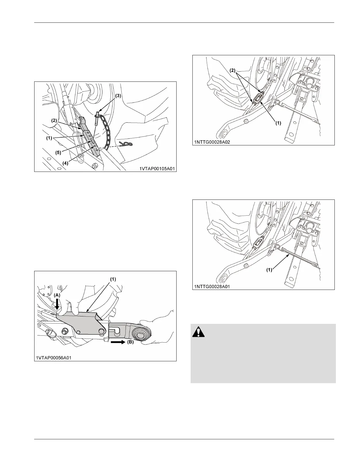
2. After aligning satisfactorily, insert the set-pin
through any one of the 4 holes on the outer tube
that align with one of the holes on the inner bar.
Both stabilizers will be locked.
If the set-pin is inserted through the slot to engage
one of the holes on the inner bar, a limited degree
of sway will be permitted.
(1) Outer tube
(2) Inner bar
(3) Set-pin
(4) Hole
(5) Slot
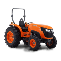
2.5 Adjusting the telescopic lower links
[MX5400 (4WD) / MX6000]
To attach an implement, follow the instructions in this
section.
1. Push the levers, pull out the ends of lower links,
and attach to the implement.
2. Back up the tractor slightly to make sure that the
lower links are pushed in securely.
(1) Lever
(A) Push
(B) Pull out
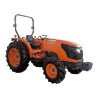
2.6 Adjusting the check chains [MX5400
(2WD)]
1. Adjust the turnbuckle to control the horizontal sway
of the implement.
(See Hydraulic control unit use reference chart on
page 96)
2. After adjustment, retighten the lock nut.
(1) Turnbuckle (2) Lock nut
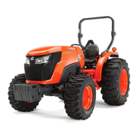
2.7 Lower link holder [MX5400 (2WD)]
When operating the tractor without a 3-point hitch
implement, it is necessary to lock the lower links to
prevent them from hitting the rear wheels of the tractor.
(1) Lower link holder
DRAWBAR
WARNING
To avoid personal injury or death:
• Never pull from the top link, the rear axle, or any
point above the drawbar. Pulling from the top
link, the rear axle, or any point above the
drawbar could cause the tractor to tip over
rearward.
For details about the drawbar load, see IMPLEMENT
LIMITATION TABLES on page 27.
3-POINT HITCH 3-POINT HITCH AND DRAWBAR