Lifting Arms 223
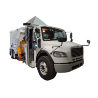
3. Locate the holding valve on the in/out cylinder (see Figure 10-18).
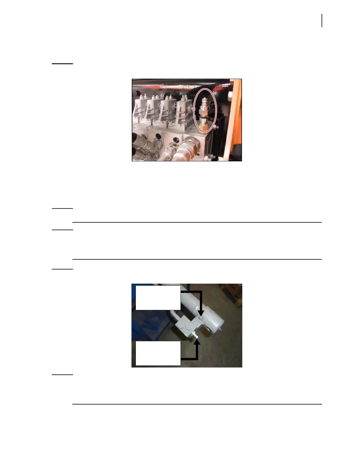
4. Connect a pressure gauge to the automated arm valve.
Figure 10-17
Quick coupler for pressure gauge
5. Start the engine and engage the hydraulic pump.
6. Using a lever on the valve, manually extend the Right Hand™ arm gradually.
7. If the gauge does not indicate a pressure of about 650 psi when the automated arm starts
extending, adjust the in/out holding valve adjustment screw to set the pressure properly.
NOTE: Turn the screw counter-clockwise to increase pressure or clockwise to reduce pressure.
NOTE: This pressure value of 650 psi is a reference value; it could be more or less. It all depends on
how much pressure the in/out holding valve needs to resist to an arm slide pull force of at least
1600 lbs up to a maximum of 1900 lbs, at which time the valve must open.
Figure 10-18
Holding valve adjustment screw (in/out cylinder)
NOTE: If the cushioning effect on the retraction stroke needs to be adjusted, simply turn the
cushioning adjustment screw accordingly: clockwise to increase cushioning effect; counter-
clockwise to reduce it. The cushioning effect on the extension stroke cannot be adjusted.
Holding valve
adjustment
screw
Cushioning
adjustment
screw